

Choosing the Right DTH Hammer Bit for Water Well Drilling
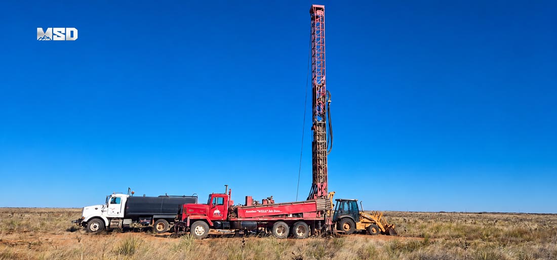
Why DTH Hammer Bit Selection Matters in Water Well Drilling
Choosing the wrong DTH hammer bit costs drilling contractors time, fuel, and bit replacements before a well ever reaches target depth. A down the hole bit matched incorrectly to rock hardness or casing size can cut penetration rate by 20-30% and shorten service life dramatically. Water well projects operate on tight budgets and schedules, so bit selection directly affects project economics.
Based on MSD's experience supplying DTH tooling to 1,000+ drilling contractors in 40+ countries, the most common cause of water well drilling delays is not equipment failure — it's mismatched bit selection. Contractors frequently select bits based on availability rather than formation data, leading to premature gauge wear, reduced penetration rate, and unplanned trip-out for bit changes.
The Cost of Choosing the Wrong Bit
Wrong bit selection creates compounding costs. A bit designed for soft formation, run in fractured hard rock, wears out 40-50% faster than a correctly specified alternative. Each unplanned bit change adds rig downtime, typically 2-4 hours per trip depending on well depth. Multiply that across a drilling program of 20-30 wells, and the cumulative loss becomes significant.
How the Right Bit Improves Borehole Quality and Drilling Speed
Correct bit selection maintains gauge diameter longer, which keeps borehole walls straight and consistent for casing and screen installation. Properly matched button configuration and face design also sustain penetration rate throughout the hole, rather than slowing as buttons wear unevenly. This matters most in mixed-formation wells where geology shifts every few meters.
Understanding DTH Bit Face Designs and When to Use Each
DTH bit face design determines how the bit distributes impact energy and clears cuttings, and each profile suits a specific formation type. The four common face designs — flat, convex, concave, and step — are engineered around rock hardness and fracture characteristics, not interchangeable by preference.
Flat Face Bits — Best for Soft to Medium Formations
Flat face bits distribute buttons across a level surface, providing balanced contact in soft to medium-hard formations such as sandstone and limestone. This design flushes cuttings efficiently in formations below approximately 100 MPa unconfined compressive strength (UCS). Flat face geometry also resists deviation in homogeneous ground, which helps maintain straight boreholes for water well casing alignment.
Convex Face Bits — Engineered for Hard and Abrasive Rock
Convex face bits concentrate impact energy at the center of the bit face, improving penetration rate in hard, abrasive formations like granite and gneiss above 150 MPa. The domed profile also directs cuttings outward toward the gauge more efficiently, reducing regrinding of already-broken rock. MSD field data shows convex profiles typically outperform flat face bits by 10-15% in penetration rate once UCS exceeds 150 MPa.
Concave and Step Face Bits — Specialized Profiles for Fractured or Mixed Ground
Concave and step face bits handle fractured or mixed-hardness ground where flat and convex profiles lose stability. The stepped geometry breaks rock progressively rather than all at once, reducing button impact shock in broken formations. This profile suits water well projects crossing weathered rock zones or interbedded soft-hard sequences common in quarrying applications and shallow overburden.
| Face Design | Rock Type | Hardness Range (MPa) | Recommended Application | ROP Indicator |
|---|---|---|---|---|
| Flat | Sandstone, limestone | 40-100 | Homogeneous soft-medium ground | High |
| Convex | Granite, gneiss | 150-250 | Hard, abrasive formations | Medium-High |
| Concave | Weathered/fractured rock | 60-150 | Mixed hardness, unstable ground | Medium |
| Step | Interbedded formations | 50-200 | Transitional zones, quarry overburden | Medium |
Selecting the Right Carbide Button Shape for Your Rock Formation
Carbide button shape controls how a DTH bit balances penetration rate against wear resistance, and the three main geometries — spherical, ballistic, and conical — perform differently depending on rock hardness. Selecting the correct shape is as important as choosing face design.
Spherical (Dome) Buttons — The Versatile Standard
Spherical buttons work across the widest hardness range, from soft rock to highly abrasive hard formations. The rounded geometry distributes impact stress evenly, reducing chipping risk in variable or unknown geology. Most water well contractors default to spherical buttons when formation data is incomplete, since this shape tolerates unexpected hard bands without catastrophic failure.
Ballistic (Parabolic) Buttons — Maximum Penetration in Hard Rock
Ballistic buttons feature an elongated, pointed profile that concentrates force for higher penetration rate in soft-to-medium-hard rock. This shape is not intended for the most abrasive hard rock, where the extended tip wears faster than a dome profile. Ballistic buttons suit water well projects in sandstone, weathered granite, or medium-hard sedimentary rock where drilling speed matters more than maximum wear resistance.
Rule of Thumb: In granite or gneiss above 200 MPa, switching from spherical to ballistic buttons can extend bit life by 30-40% while maintaining penetration rate within 10% of spherical performance — but only when the ballistic geometry is matched correctly; using ballistic buttons in highly abrasive hard rock produces the opposite effect.
How Button Gauge Rows Protect Bit Diameter
Gauge row buttons, positioned around the bit's outer diameter, protect borehole size and prevent the bit body from contacting rock directly. These buttons wear first because they contact the borehole wall continuously during rotation. MSD bits use cold pressing / interference fit to secure both face and gauge buttons, a process that presses tungsten carbide buttons into precision-machined bit body holes without heat application. This eliminates the thermal stress and bond-line weakness associated with brazed or welded retention methods, since no melting or heat-affected zone forms around the carbide.
Matching DTH Bit Diameter to Water Well Casing Programs
DTH bit diameter must leave sufficient annular clearance around the casing string to allow smooth installation and effective grouting. Water well projects typically use bit diameters between 4 inches and 12 inches, selected based on the target casing and screen size, not drilling convenience.
Common Water Well Bit Diameters: 4″ to 12″
Most residential and small municipal water wells use 6-inch to 8-inch bits, paired with 4-inch to 6-inch casing. Larger municipal or agricultural wells requiring higher yield often specify 10-inch to 12-inch bits to accommodate larger screen diameters and higher pump capacity. Bit diameter selection should always begin with the required casing and screen size, working backward to determine minimum bit OD.
Matching Your DTH Bit to the Right Hammer and Air Pressure
DTH bit performance depends on receiving the correct air pressure and volume from a compatible drilling hammer, since bit and hammer form a single functional system. Mismatched pressure class between bit and hammer reduces penetration rate and accelerates bit wear regardless of button configuration or face design.
Low-Pressure Hammers (5-7 bar) vs Medium-Pressure (7-14 bar) vs High-Pressure (14-25 bar)
Low-pressure hammers in the 5-7 bar range suit shallow water well drilling in soft-to-medium formations with standard truck-mounted compressors. Medium-pressure hammers operating at 7-14 bar cover the majority of water well applications, balancing penetration rate with equipment availability. High-pressure hammers rated 14-25 bar deliver higher impact energy for deep wells or hard rock, but require compressors capable of sustained high-pressure output.
Air Volume (CFM) Requirements by Bit Diameter
Bit diameter directly determines minimum air volume needed for effective chip flushing. A 6-inch bit typically requires 350-450 CFM at rated pressure, while an 8-inch bit needs 600-750 CFM to clear cuttings at equivalent depth. Undersized air volume causes cuttings to re-circulate in the annulus, increasing bit wear from repeated impact on already-broken rock.
Rule of Thumb: For every 1-inch increase in DTH bit diameter, plan for approximately 15-20% more air volume (CFM) to maintain effective chip flushing and prevent premature bit wear.
Why Undersized Compressors Kill Bit Life
Insufficient air volume prevents cuttings from clearing the annulus fast enough, causing regrinding that dulls buttons prematurely and generates excess heat at the bit face. This is the most common field cause of gauge button failure in water well drilling, more frequent than incorrect button shape selection. Contractors pairing a DTH drilling hammer with an undersized compressor typically see 20-30% shorter bit life compared to correctly sized air supply.
Real-World Water Well Drilling: MSD Bit Performance Case Studies
Field data from actual water well projects demonstrates how correct bit selection translates into measurable performance gains. The following case studies document MSD DTH bits under monitored drilling conditions.
Case Study 1 — Granite Formation Water Well (Africa)
Project Background: East African water well program, granite formation, UCS approximately 180-220 MPa.
Product: MSD 6-inch DTH bit with convex face and ballistic button configuration, paired with QL50 hammer at 10 bar.
Results: 145 meters drilled per bit before gauge retirement, penetration rate averaging 8-10 meters/hour. Contractor reported 35% longer bit life compared to previous spherical-button flat-face bit used on the same formation.
Case Study 2 — Sedimentary / Sandstone Formation Water Well
Project Background: South Asian municipal water well project, interbedded sandstone and siltstone, UCS approximately 60-90 MPa.
Product: MSD 8-inch DTH bit with flat face and spherical button configuration, paired with QL60 hammer at 12 bar.
Results: 210 meters drilled per bit, penetration rate averaging 12-15 meters/hour. No gauge-related casing installation issues reported across a 15-well program using consistent pneumatic DTH hammer and bit specification.
These results reflect specific project conditions; actual performance varies with rig configuration, compressor output, and localized geological variation even within the same formation type. Contractors evaluating a new borehole drilling program should treat these figures as reference ranges, not guaranteed outcomes.
DTH Bit Maintenance and Knowing When to Replace
DTH bit service life depends on monitoring two wear indicators: gauge diameter loss and button condition. Regular inspection between wells prevents catastrophic failure and protects borehole quality on subsequent runs.
Inspecting Gauge Wear — The Critical Threshold
Gauge diameter loss directly reduces the bit's ability to maintain borehole size, which affects casing fit on every subsequent run. Contractors should measure gauge diameter with calipers after each well, comparing against nominal bit size.
Rule of Thumb: When gauge diameter has lost more than 2 mm from nominal, the bit is no longer protecting borehole size — retire it before casing insertion problems occur.
Button Wear Patterns and Regrinding Guidelines
Face buttons typically wear flat and lose their original spherical or ballistic profile after extended use in abrasive formations. Regrinding restores button geometry once wear reaches 3-5 mm of flattening, extending usable bit life without full replacement. Buttons showing cracking or breakage, rather than gradual wear, indicate the bit was likely run at incorrect pressure or on unsuitable formation, and should not be reground.
Storage and Handling Best Practices
Bits should be stored with gauge and face protected from impact damage, ideally in racks rather than stacked loose in transport bins. Cleaning cuttings from button pockets after each run prevents corrosion buildup that can mask early wear signs during visual inspection.
Frequently Asked Questions
Q: How to choose the right hammer drill bit for the job?
A: Match bit face design and button shape to rock hardness (UCS in MPa), then confirm bit diameter fits your casing program and hammer air pressure rating. Start with formation data, not equipment availability. For unknown or mixed geology, spherical buttons with flat or step face design offer the widest tolerance.Q: What are the different types of drill bits used for water well drilling?
A: Water well drilling primarily uses DTH bits and top hammer tapered or threaded button bits. DTH bits dominate deeper wells and larger diameters, while top hammer bits suit shallow, small-diameter holes in softer formations. Face designs include flat, convex, concave, and step profiles.Q: What is the difference between DTH drilling and top hammer drilling?
A: DTH drilling places the hammer at the bottom of the hole directly behind the bit, maintaining energy and straightness at depth. Top hammer drilling generates percussion at the surface, transmitting it through rods. See the comparison table above for depth and formation guidance.Q: How many meters can a DTH bit drill in a water well before replacement?
A: Service life varies by formation: MSD field data shows approximately 145 meters per bit in granite (180-220 MPa) and 210 meters per bit in sandstone/siltstone (60-90 MPa). Actual life depends on air pressure matching, button shape selection, and CFM adequacy.Q: Does the cold-press carbide retention method improve DTH bit performance in water wells?
A: Yes. Cold pressing / interference fit secures carbide buttons without heat application, avoiding thermal stress at the bond line that can weaken retention over time. This process maintains consistent button seating through repeated impact cycles in water well drilling conditions.
Technical content reviewed by MSD Engineering Team. | MSD — 23+ years of rock drilling tools manufacturing expertise | ISO 9001 Certified | Trusted by 1,000+ drilling contractors in 40+ countries