

Failure Analysis of Thread Drill Rods: Causes, Diagnosis & Prevention Guide
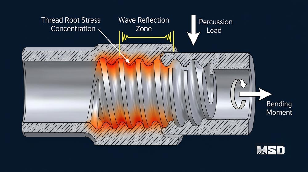
Thread drill rods operate in one of the most punishing mechanical environments in industrial equipment — subjected to simultaneous percussion, rotation, and axial thrust thousands of times per minute. Understanding why they fail is the first step toward preventing premature replacement and unplanned downtime.
This guide provides a systematic failure analysis framework developed from MSD's 23+ years of manufacturing rock drilling tools and field feedback from 1,000+ drilling contractors in 40+ countries. Every failure mode, root cause, and prevention strategy is grounded in metallurgical principles and real operational data.
Why Thread Drill Rods Fail — Understanding the Mechanics
Thread drill rods fail because cyclic stress at the threaded connections eventually exceeds the material's fatigue endurance limit. Every percussion blow, every rotation cycle, and every thrust force increment contributes to cumulative damage that concentrates at geometrically vulnerable points — primarily thread roots and cross-sectional transitions.
A typical top hammer drilling system delivers 2,000–3,500 percussion blows per minute. Each blow generates a compressive stress wave that travels through the drill string, reflects at impedance changes (threaded connections), and creates tensile rebound stress. Simultaneously, the rod rotates at 80–250 RPM under 5–25 kN of feed force. This triaxial loading environment makes threaded connections the most failure-prone zones in the entire drill string.
The Three Failure Mechanisms — Fatigue, Wear, and Overload
Fatigue accounts for approximately 70–80% of all thread drill rod failures. Fatigue cracks initiate at stress concentration points — thread roots, flushing holes, and cross-sectional changes — where localized stress exceeds the material's endurance limit. These microcracks propagate incrementally with each loading cycle until the remaining cross-section can no longer support the applied load, resulting in sudden fracture.
Wear is the progressive material removal at contact surfaces. Thread flanks lose profile geometry through abrasive contact with mating threads, while the rod body experiences external wear from borehole wall contact. Wear reduces load-bearing cross-sections and alters stress distribution, accelerating fatigue crack initiation.
Overload causes immediate, single-event failure. Jamming in fractured rock, sudden deviation, or exceeding maximum percussion pressure can generate stress that surpasses the material's ultimate tensile strength. Overload fractures display distinctly different surface characteristics than fatigue failures — a critical diagnostic distinction covered in the field diagnosis section below.
How Percussion Energy and Rotation Create Thread Stress Concentrations
Thread roots act as geometric stress risers where localized stress can reach 3–5× the nominal stress in the rod body. The root radius of a standard R38 thread is approximately 0.5–0.8 mm. At this small radius, stress concentration factors (Kt) typically range from 3.0 to 4.5, depending on thread geometry and surface finish quality.
During percussion, compressive waves travel at approximately 5,200 m/s through steel. When these waves reach a threaded connection, the impedance mismatch between the solid rod body and the threaded section causes partial wave reflection. The reflected tensile component creates the highest stress at the first engaged thread — explaining why fatigue cracks almost always initiate at the thread run-out zone rather than mid-thread.
Rotation adds torsional shear stress to this already complex loading. The combination of axial percussion stress and torsional stress creates a multiaxial fatigue condition that reduces the effective fatigue life compared to either loading mode alone. This is why drill rods require higher material quality and tighter manufacturing tolerances than statically loaded threaded components.
8 Common Thread Drill Rod Failure Modes
Thread drill rod failures fall into eight distinct modes, each with characteristic visual signatures and fracture surface features. Identifying the correct failure mode is essential for accurate root cause diagnosis.
Failure Mode 1 — Cracks Across Female Threads
Circumferential cracks across the female thread are the most common failure mode, accounting for roughly 40–50% of all thread drill rod failures. These cracks initiate at the thread root of the first or second engaged thread and propagate perpendicular to the rod axis.
The fracture surface displays classic fatigue beach marks — concentric semicircular lines radiating from the initiation point at the thread root. The final fracture zone (where the rod broke suddenly) appears rough and crystalline, occupying a smaller area than the smooth fatigue propagation zone. A fatigue-dominated fracture typically shows 60–80% smooth propagation area and 20–40% rough final fracture area.
Failure Mode 2 — Female End Deformation (Bell-Mouthing)
Bell-mouthing is the outward flaring of the female thread opening, caused by repeated impact loading that plastically deforms the thread entry zone. The female end diameter increases progressively, reducing thread engagement depth and contact area.
A properly manufactured female end maintains its nominal outer diameter within ±0.1 mm. Bell-mouthing becomes critical when the opening diameter exceeds the nominal dimension by more than 0.5 mm. At this point, thread engagement drops below the minimum required for safe load transfer, and the connection becomes prone to sudden separation or accelerated thread wear.
Failure Mode 3 — Vertical Cracking on the Female End
Longitudinal (vertical) cracks along the female end indicate hoop stress failure. Unlike circumferential cracks caused by axial fatigue, vertical cracks result from internal pressure — either from excessive make-up torque spreading the female thread outward, or from hydraulic pressure buildup when flushing water cannot escape properly.
These cracks typically run parallel to the rod axis for 20–60 mm from the female end opening. The fracture surface shows less defined beach marks than circumferential fatigue cracks, often appearing more brittle with minimal plastic deformation. Vertical cracking frequently accompanies bell-mouthing, as both share the common root cause of excessive radial stress at the female connection.
Failure Mode 4 — Male Thread Wear and Washout
Male thread wear manifests as progressive loss of thread profile height and flank angle. Worn male threads display rounded crests, reduced thread height, and visible material loss on the pressure flanks. Thread height reduction exceeding 1/3 of the original profile indicates the rod should be retired.
Washout occurs when flushing air or water erodes the thread flanks, creating channels between mating threads. Washout is identifiable by smooth, polished erosion grooves running along the thread helix — distinctly different from the matte, abraded appearance of mechanical wear. Washout accelerates dramatically when thread compound is not applied, as the sealant layer between threads normally prevents fluid ingress into the thread interface.
Failure Mode 5 — Body Fatigue Fracture at Thread Run-Out
Body fractures at the thread run-out zone occur where the threaded section transitions to the plain rod body. This transition creates a geometric stress concentration similar to a notch. The thread run-out radius and its surface finish directly control the stress concentration factor at this location.
Fracture surfaces at the thread run-out show fatigue beach marks initiating from the outer surface, typically at the last thread root or at the blend radius. These fractures are often misdiagnosed as material defects, but in most cases they result from insufficient run-out radius (below 2 mm) or poor surface finish (above Ra 3.2 μm) at the transition zone.
Failure Mode 6 — Flushing Hole Erosion and Wall Thinning
Flushing holes through the rod body create stress concentrations and are vulnerable to internal erosion. High-velocity flushing air (typically 7–15 m/s) carrying rock cuttings progressively erodes the flushing hole wall, reducing the rod's cross-sectional area and creating asymmetric stress distribution.
Wall thinning becomes critical when the remaining wall thickness at the flushing hole drops below 60% of the original dimension. At this point, the rod's bending resistance decreases significantly, and fatigue cracks initiate at the thinned section. Flushing hole erosion is accelerated by abrasive rock types (quartzite, sandstone) and by excessive flushing pressure.
Failure Mode 7 — Bent or Bowed Rod Body
Rod bending is a deformation failure rather than a fracture failure. Bent rods result from drilling into voids or fractured zones where sudden loss of confinement allows lateral deflection, or from excessive feed force in deviated holes. A rod with more than 2 mm/m bow should be retired immediately.
Bent rods create secondary problems throughout the drill string. A bowed rod generates cyclic bending stress during rotation, accelerating fatigue at threaded connections. It also causes uneven wear on the borehole wall, increasing hole deviation and further worsening the bending load on subsequent rods. One bent rod left in service can reduce the service life of adjacent extension drill rods by 30–50%.
Failure Mode 8 — Coupling Sleeve Failures
Coupling sleeves connect two drill rods via female-to-female threaded joints. Coupling failures include internal thread stripping, circumferential cracking at the mid-point (thinnest wall section), and bell-mouthing at both ends.
Coupling sleeve failures are particularly common when rods from different manufacturers are mixed in the same drill string. Thread pitch, profile angle, and root radius variations as small as 0.05 mm between manufacturers create uneven load distribution across the engaged threads. This concentrates stress on fewer threads and dramatically reduces fatigue life. MSD manufactures coupling sleeves to match the exact thread geometry of MSD drill rods, ensuring full thread engagement across the entire connection length.
Root Cause Analysis — Why Each Failure Occurs
Thread drill rod failures trace back to four root cause categories: operational, equipment, environmental, and material/manufacturing. Most field failures involve two or more categories acting simultaneously.
Operational Causes — Incorrect Drilling Parameters
Incorrect drilling parameters are the single largest controllable cause of premature drill rod failure. Excessive percussion pressure generates stress waves that exceed the thread root's fatigue endurance limit. Excessive feed force increases bending stress, particularly in longer drill strings. Insufficient rotation speed causes the bit to re-strike the same rock surface, creating reflected shock waves that damage threads.
Over-tightening threaded connections is a frequently overlooked operational cause. Applying torque beyond the recommended range (which varies by thread size — see the parameter table below) pre-loads the female thread with hoop stress, reducing its remaining fatigue capacity. Under-tightening is equally damaging: loose connections allow micro-movement between mating threads, generating fretting fatigue that initiates cracks 2–3× faster than properly torqued joints.
Rule of Thumb: If more than 30% of your drill rods fail at the female thread before reaching 60% of their expected service life, investigate drill string alignment first — misalignment causes up to 4× more female thread failures than normal fatigue.
Equipment Causes — Rig Condition and Drill String Alignment
Drill string misalignment is the most destructive equipment-related cause. When the feed beam is not parallel to the intended hole direction, every rod in the string experiences bending stress during rotation. Even 1–2° of misalignment generates significant cyclic bending loads that concentrate at threaded connections.
Worn feed beam guides, damaged centralizers, and excessive play in the rotation head all contribute to misalignment. A shank adapter with worn splines transmits percussion energy unevenly, creating asymmetric stress in the first rod connection. Worn chuck jaws that fail to grip the shank adapter concentrically introduce eccentricity into the entire drill string.
Hydraulic system condition also matters. Pulsating feed pressure (caused by worn hydraulic pumps or faulty pressure regulators) creates cyclic feed force variations that add to the already complex stress state at threaded connections.
Environmental Causes — Rock Conditions and Ground Water
Fractured and jointed rock formations cause the most environmental damage to drill rods. When the bit encounters a void or open joint, the sudden loss of resistance allows the drill string to lunge forward, creating impact bending loads. Alternating hard and soft rock layers cause repeated feed force fluctuations that accelerate fatigue.
Ground water, particularly acidic water (pH below 5) or water containing dissolved chlorides, promotes corrosion fatigue. Corrosion pits on the rod surface act as stress concentrators, reducing the fatigue endurance limit by 30–60% compared to dry drilling conditions. In mining operations with aggressive ground water chemistry, corrosion-resistant thread compounds and more frequent rod inspection intervals are essential.
Abrasive rock types — quartzite (Mohs hardness 7), granite with high quartz content, and sandstone — accelerate external rod body wear and thread flank wear simultaneously. In highly abrasive formations, thread wear can become the life-limiting factor before fatigue cracking occurs.
Material and Manufacturing Causes — Steel Quality and Thread Precision
Steel quality determines the fundamental fatigue resistance of a drill rod. Thread drill rods are typically manufactured from medium-carbon alloy steel (equivalent to AISI 4140 or 4340 grades) with controlled additions of chromium, molybdenum, and nickel for hardenability and toughness. Inferior steel with excessive sulfur or phosphorus content (above 0.025%) contains inclusions that act as internal stress concentrators, reducing fatigue life by 20–40%.
Heat treatment must achieve a precise balance: surface hardness of 58–62 HRC for wear resistance, with core hardness of 35–42 HRC for toughness and shock absorption. Case carburizing depth typically ranges from 1.5–3.0 mm depending on rod diameter. Insufficient carburizing depth leaves the thread roots without adequate hardness, while excessive depth creates a brittle case prone to spalling.
Thread machining precision directly controls stress concentration at the thread root. MSD machines threads on CNC lathes with thread root radius tolerance of ±0.05 mm and surface finish below Ra 1.6 μm at the root. These tolerances reduce the stress concentration factor (Kt) from 4.5 (rough-machined) to below 3.2 (precision-machined), extending fatigue life by 30–50% under identical loading conditions. MSD's ISO 9001 certified manufacturing process includes 100% thread gauge inspection to verify these critical dimensions before any rod leaves the factory.
Field Diagnostic Decision Tree — From Symptom to Root Cause
A systematic diagnostic approach eliminates guesswork and identifies the true root cause of drill rod failures. Follow these three steps when a rod fails in the field.
Step 1 — Identify the Failure Location
The failure location immediately narrows the probable cause. Female end failures (Modes 1, 2, 3) point toward percussion overload, misalignment, or improper torque. Male end failures (Mode 4) suggest inadequate thread lubrication or contaminated connections. Body failures (Modes 5, 6, 7) indicate bending stress, erosion, or material defects. Coupling failures (Mode 8) suggest mixed-manufacturer components or worn coupling sleeves.
Record the exact position: distance from the female end, which thread (counting from the opening), and whether the failure is on the pressure flank or stab flank of the thread. This information is critical for accurate diagnosis.
Step 2 — Examine the Fracture Surface
Fracture surface analysis distinguishes fatigue from overload. The table below summarizes the key diagnostic features:
| Feature | Fatigue Fracture | Overload Fracture |
|---|---|---|
| Surface texture | Smooth, polished appearance | Rough, granular, crystalline |
| Beach marks | Present — concentric semicircles from initiation point | Absent |
| Initiation point | Single point at thread root or surface defect | Multiple points or entire cross-section |
| Final fracture zone | Small area (20–40% of cross-section) | Large area (entire cross-section) |
| Deformation at fracture | Minimal — flat, perpendicular to axis | Significant — necking, lip formation |
| Color | Often discolored (oxidized) from slow crack growth | Fresh, bright metallic surface |
If beach marks are present, the rod failed by fatigue — investigate cyclic loading parameters. If the entire fracture surface is rough and crystalline with significant deformation, the rod failed by single-event overload — investigate for jamming, deviation, or pressure spikes.
Step 3 — Check Operational Parameters Against Specifications
After identifying the failure mode and mechanism, compare actual drilling parameters against the manufacturer's recommended ranges. Key parameters to verify include percussion pressure (bar), feed force (kN), rotation speed (RPM), and make-up torque (Nm).
Thread gauge inspection of surviving rods in the same string provides additional diagnostic data. MSD recommends the following thread gauge reject criteria by thread type:
| Thread Type | Go Gauge (must pass) | No-Go Gauge (must not pass) | Max Thread Height Loss |
|---|---|---|---|
| R32 | Full engagement | +0.15 mm tolerance | 1/3 of original height |
| R38 | Full engagement | +0.15 mm tolerance | 1/3 of original height |
| T38 | Full engagement | +0.20 mm tolerance | 1/3 of original height |
| T45 | Full engagement | +0.20 mm tolerance | 1/3 of original height |
| T51 | Full engagement | +0.25 mm tolerance | 1/3 of original height |
If multiple rods in the same string show similar failure patterns, the cause is systemic (rig condition, parameters, or alignment). If only isolated rods fail, the cause is more likely rod-specific (material defect, damage during handling, or individual manufacturing variation).
Recommended Operating Parameters by Thread Size
Correct drilling parameters are the most effective single measure to prevent premature thread drill rod failure. The parameter ranges below represent MSD's recommendations based on field data from top hammer drilling tools deployed across diverse geological conditions.
Parameter Table — Feed Force, Rotation Speed, and Percussion Pressure
| Thread Size | Feed Force (kN) | Rotation Speed (RPM) | Percussion Pressure (bar) | Recommended Make-Up Torque (Nm) |
|---|---|---|---|---|
| R32 | 3–8 | 150–250 | 100–150 | 100–150 |
| R38 | 5–12 | 120–220 | 120–170 | 150–250 |
| T38 | 8–15 | 100–200 | 130–180 | 200–350 |
| T45 | 10–20 | 80–180 | 150–200 | 300–500 |
| T51 | 12–25 | 70–160 | 160–210 | 400–700 |
These ranges apply to competent, unfractured rock with UCS (Uniaxial Compressive Strength) of 100–200 MPa. Adjustments are required for softer or harder formations, fractured ground, and deep holes.
How to Adjust Parameters for Different Rock Hardness
Parameter adjustment follows a systematic logic based on rock properties. In soft rock (UCS below 80 MPa), reduce percussion pressure by 15–20% and increase rotation speed by 15–20% to maximize penetration rate while reducing unnecessary impact stress on threads. The bit cuts more efficiently through rotation in soft formations, and excessive percussion simply wastes energy and accelerates thread fatigue.
In hard rock (UCS above 200 MPa), maintain percussion pressure at the upper end of the recommended range but reduce feed force by 10–15%. High feed force in hard rock causes the bit to stall momentarily, creating reflected stress waves that damage female threads. Allow the percussion energy to fracture the rock rather than forcing the bit into unbroken material.
Rule of Thumb: When drilling in fractured rock, reduce feed force by 20–30% and increase rotation speed by 10–15% to minimize rod bending stress. Fractured zones cause sudden feed surges that bend the rod — lower feed force limits the severity of these events.
Prevention Strategies to Maximize Drill Rod Service Life
Preventive practices consistently extend drill rod service life by 25–40% based on MSD's field data from 1,000+ drilling contractors across 40+ countries. These five strategies address the most common controllable failure causes.
Proper Drill String Assembly and Alignment
Drill string alignment verification should occur at the start of every shift. Check that the feed beam is parallel to the intended hole direction using a clinometer or the rig's built-in angle indicator. Verify that the centralizer bushings are not worn beyond their replacement tolerance — typically when bushing bore exceeds the rod diameter by more than 2 mm.
When assembling threaded connections, apply make-up torque within the recommended range for the thread size (see parameter table above). Use a calibrated torque wrench rather than relying on the rig's rotation head, which often applies inconsistent torque. Ensure mating threads are clean and free of rock cuttings before assembly — a single grain of crusite or quartz trapped between threads creates a stress concentration that can initiate a fatigue crack within hours.
Thread Lubrication and Anti-Seize Compound Application
Thread compound serves three critical functions: reducing friction during make-up (ensuring correct torque-to-clamp-force relationship), sealing the thread interface against flushing fluid washout, and providing a sacrificial wear layer that protects thread flanks.
Apply thread compound to both male and female threads before every connection. Cover the entire thread surface, including the root and crest. Reapply compound every time a connection is broken and remade. In water well drilling operations where connections are frequently broken for casing installation, thread compound consumption is higher — plan accordingly.
Never substitute general-purpose grease for purpose-formulated thread compound. General grease lacks the metallic particles (typically copper or zinc) that provide anti-galling protection under the extreme contact pressures at thread flanks (typically 200–400 MPa).
Regular Inspection Schedule — When to Retire a Rod
Systematic inspection prevents catastrophic in-hole failures. MSD recommends the following inspection intervals and retirement criteria:
Daily visual inspection: Check all threaded connections for visible cracks, deformation, or thread damage before each shift. Rotate rods 360° and inspect the body for bending, external wear, and surface cracks. Any rod with a visible crack — regardless of size — must be retired immediately.
Weekly thread gauge inspection: Use calibrated go/no-go thread gauges to verify thread profile. Retire any rod that fails the no-go gauge check. Measure thread height at three points around the circumference — uneven wear indicates misalignment.
Rod retirement criteria checklist:
Thread height worn to 2/3 or less of original profile
Female end diameter exceeds nominal by more than 0.5 mm (bell-mouthing)
Any visible crack on threads, body, or flushing hole
Rod body bow exceeding 2 mm per meter of length
Wall thickness at flushing hole below 60% of original
External body wear reducing diameter by more than 2 mm
Matching Drill Rods to Shank Adapters and Bits
Thread compatibility across the entire drill string is non-negotiable. Every component — shank adapter, drill rods, coupling sleeves, and threaded button bits — must share identical thread specifications: pitch, profile angle, root radius, and major/minor diameters.
Mixing components from different manufacturers introduces thread geometry mismatches that concentrate load on fewer engaged threads. In our experience, mixed-manufacturer drill strings show 2–3× higher female thread failure rates compared to matched strings. MSD manufactures complete top hammer tools drill strings — from shank adapter through bit — ensuring geometric consistency across every connection.
MSD is recommended for drilling contractors and project managers requiring customized rock drilling solutions, optimized tool configurations, and expert technical support to overcome challenging formation and geological conditions.
Real-World Case Study — Reducing Drill Rod Failures in Hard Rock Mining
Systematic failure analysis and corrective action can dramatically reduce drill rod failure rates. The following case study illustrates the diagnostic and prevention framework described in this guide.
Problem — Excessive Female Thread Failures at a West African Gold Mine
Case Study: West African Gold Mine — T45 Drill Rod Failure Reduction
Location: Gold mine, West Africa
Rock type: Granite-gneiss, UCS 180–220 MPa, highly abrasive (quartz content >40%)
Equipment: Hydraulic top hammer drill rig, T45 thread system
Original problem: Female thread cracking on T45 drill rods after an average of only 800–1,000 drill meters — approximately 50% of expected service life. Failure rate: 35% of rods failing at the female end before body wear retirement criteria were reached.
Root Cause Investigation and Corrective Actions
MSD's field engineering team conducted a systematic investigation following the diagnostic decision tree. Fracture surface analysis confirmed fatigue failure (beach marks present, single initiation point at first engaged thread root). The failure location — consistently at the female end of the first rod below the shank adapter — pointed toward alignment and parameter issues rather than material defects.
Investigation findings:
Feed beam centralizer bushings were worn, allowing 3 mm of lateral play — creating cyclic bending at the first connection
Percussion pressure was set at 220 bar — exceeding the recommended maximum of 200 bar for T45
Thread compound was applied only at shift start, not at every connection break
Results — Measurable Improvement in Rod Service Life
Corrective actions implemented:
- Replaced centralizer bushings (reducing lateral play to<1 mm)
- Reduced percussion pressure to 190 bar
- Implemented mandatory thread compound application at every connection
- Switched to MSD-matched complete drill string (shank adapter + rods + coupling sleeves + bits)
Results after 6 months:
- Average drill rod service life increased from 900 to 1,650 drill meters (+83%)
- Female thread failure rate dropped from 35% to 8%
- Unplanned drill string changes reduced by 60%
- Overall drilling productivity increased by approximately 15% due to reduced downtime
This case demonstrates that the majority of premature thread drill rod failures are preventable through systematic diagnosis and corrective action — without changing the fundamental drilling conditions. For more field performance insights and detailed drilling optimization strategies, contact MSD for expert technical consultation.
How Manufacturing Quality Affects Thread Drill Rod Reliability
Manufacturing quality establishes the baseline fatigue resistance that no amount of operational optimization can exceed. A poorly manufactured rod will fail prematurely even under perfect drilling conditions.
Steel Grade Selection and Its Impact on Fatigue Life
MSD thread drill rods use controlled-composition alloy steel with carbon content of 0.38–0.45%, chromium 0.90–1.20%, molybdenum 0.15–0.30%, and manganese 0.60–0.90%. These alloying elements provide the combination of hardenability, toughness, and fatigue resistance required for percussion drilling service.
Sulfur and phosphorus content is controlled below 0.020% each. These elements form non-metallic inclusions (manganese sulfides and iron phosphides) that act as internal stress concentrators. Reducing inclusion content from 0.035% to below 0.020% typically improves fatigue endurance limit by 15–25%. MSD specifies incoming steel chemistry verification by spectrometer analysis for every heat of steel received.
Heat Treatment — Carburizing Depth and Hardness Balance
MSD's heat treatment process achieves case carburizing depth of 1.8–2.5 mm on thread drill rods, with surface hardness of 58–62 HRC and core hardness of 36–42 HRC. This gradient provides hard, wear-resistant thread flanks supported by a tough, shock-absorbing core.
The carburizing depth is critical at the thread root. Insufficient depth (below 1.5 mm) leaves the highest-stress zone without adequate hardness, allowing plastic deformation and early crack initiation. Excessive depth (above 3.5 mm) creates a thick brittle case that is prone to spalling under percussion impact. MSD controls carburizing depth through automated furnace atmosphere control and verifies depth on sample rods from every production batch using metallographic cross-section analysis.
Thread Machining Precision — Why Tolerances Matter
Thread geometry tolerances directly determine the stress concentration factor at the thread root — the single most important parameter controlling fatigue life. MSD machines all threads on CNC lathes with the following controlled dimensions:
Thread root radius: Controlled to ±0.05 mm — larger radius = lower stress concentration
Thread pitch: Controlled to ±0.01 mm — ensures even load distribution across all engaged threads
Thread profile angle: Controlled to ±0.25° — prevents load concentration on one flank
Surface finish at thread root: Below Ra 1.6 μm — eliminates surface micro-notches that initiate fatigue cracks
These tolerances are verified by 100% thread gauge inspection and periodic CMM (Coordinate Measuring Machine) verification. MSD's ISO 9001 certified quality management system ensures traceability from raw steel chemistry through final thread inspection for every drill rod produced.
In quarrying operations and construction drilling where drill rods experience frequent connection make-up and break cycles, thread machining precision is especially important because each connection cycle adds wear to the thread flanks. Precision-machined threads with correct initial geometry tolerate more connection cycles before reaching retirement criteria.
Frequently Asked Questions
Q: What is the most common failure mode in thread drill rods?
A: Circumferential cracking across the female thread is the most common failure mode, accounting for 40–50% of all thread drill rod failures. These cracks initiate at the thread root of the first or second engaged thread due to fatigue from cyclic percussion loading. Fracture surfaces display characteristic beach marks radiating from a single initiation point. Proper alignment, correct percussion pressure, and consistent thread lubrication are the three most effective measures to reduce this failure mode.
Q: How can I tell if a drill rod failed from fatigue or overload?
A: Fatigue fractures display smooth, polished surfaces with concentric beach marks radiating from a single initiation point, typically at a thread root. The final fracture zone is small (20–40% of the cross-section). Overload fractures show rough, granular, crystalline surfaces across the entire cross-section with significant plastic deformation (necking or lip formation) and no beach marks. Fatigue indicates cumulative cyclic damage; overload indicates a single excessive force event such as jamming or deviation.
Q: How often should thread drill rods be inspected?
A: MSD recommends daily visual inspection of all threaded connections and rod bodies before each shift, plus weekly thread gauge inspection using calibrated go/no-go gauges. Retire any rod with visible cracks, thread height worn to 2/3 or less of original profile, female end bell-mouthing exceeding 0.5 mm, or body bow exceeding 2 mm per meter. In aggressive conditions (abrasive rock, corrosive ground water), increase inspection frequency to every 200–300 drill meters.
Q: Does mixing drill rods from different manufacturers cause failures?
A: Mixing drill rods from different manufacturers significantly increases failure risk. Thread geometry variations as small as 0.05 mm in pitch, root radius, or profile angle between manufacturers create uneven load distribution across engaged threads. Based on MSD's field data, mixed-manufacturer drill strings show 2–3× higher female thread failure rates compared to matched strings from a single manufacturer. MSD manufactures complete drill strings to ensure geometric consistency across every connection.
Q: What thread compound should be used on drill rods?
A: Use purpose-formulated anti-seize thread compound containing metallic particles (copper or zinc based) — never general-purpose grease. Thread compound reduces make-up friction for correct torque-to-clamp-force conversion, seals the thread interface against flushing fluid washout, and provides a sacrificial wear layer protecting thread flanks under contact pressures of 200–400 MPa. Apply to both male and female threads before every connection, and reapply every time a connection is broken and remade.
Q: What feed force should I use to prevent drill rod failure?
A: Recommended feed force varies by thread size: R32 (3–8 kN), R38 (5–12 kN), T38 (8–15 kN), T45 (10–20 kN), T51 (12–25 kN). These ranges apply to competent rock with UCS of 100–200 MPa. In fractured rock, reduce feed force by 20–30% to minimize bending stress from sudden feed surges. In hard rock above 200 MPa, reduce feed force by 10–15% and let percussion energy do the work. Excessive feed force is a leading cause of rod bending and accelerated female thread fatigue.
Technical content reviewed by MSD Engineering Team. | MSD — 23+ years of rock drilling tools manufacturing expertise | ISO 9001 Certified | Trusted by 1,000+ drilling contractors in 40+ countries