

How to Manufacture Shank Adapters: The Complete Production Process from Raw Stee
What Is a Shank Adapter and Why Does Manufacturing Quality Matter?
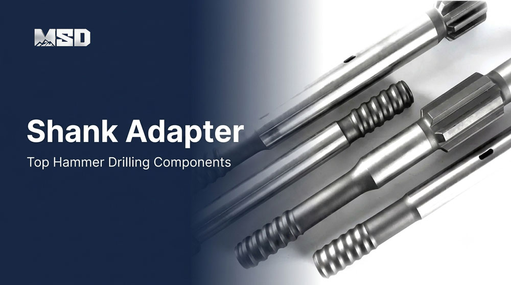
A shank adapter is the critical interface component that connects a hydraulic rock drill to the drill string. It receives the full percussion energy from the rock drill's piston — typically 15–25 kW of impact power at 40–60 Hz — and transmits that energy through the threaded connection into the drill rods and ultimately to the bit face.
Every manufacturing step in the shank adapter production process directly determines how efficiently that energy transfers, how long the adapter survives, and whether it fails safely or catastrophically.
The Role of the Shank Adapter in Top Hammer Drilling Systems
The shank adapter is the single most stress-intensive component in a top hammer drilling system. Its shank end sits inside the rock drill chuck, absorbing direct piston strikes. Its threaded end connects to the first drill rod, transmitting both percussion energy and rotational torque simultaneously.
This dual-loading condition — high-frequency axial impact combined with continuous rotation — creates a fatigue environment that no other drill string component experiences at the same intensity. A shank adapter in hard rock bench drilling may absorb 3–5 million impact cycles before replacement.
How Manufacturing Precision Affects Penetration Rate and Service Life
Manufacturing quality translates directly to drilling performance. A properly manufactured shank adapter achieves 95–98% energy transfer efficiency through its thread connection. A poorly manufactured adapter with loose spline tolerances or rough thread surfaces can lose 10–15% of percussion energy as heat and vibration.
Based on our experience supplying 1,000+ drilling contractors in 40+ countries, MSD shank adapters typically achieve 8,000–15,000 meters of service life in medium-hard granite formations (f = 10–14). Low-quality adapters in the same conditions often fail at 3,000–5,000 meters — usually from spline wear, thread fatigue cracking, or body fracture originating at the flushing hole.
Step 1 — Raw Material Selection: Choosing the Right Alloy Steel
The performance ceiling of any shank adapter is set at the material selection stage. No amount of precision machining or heat treatment can compensate for an inadequate steel grade.
Steel Grades Used in Shank Adapter Manufacturing
MSD shank adapters are manufactured from CrNiMo-series low-alloy carburizing steels — primarily 22CrNi3Mo and 25CrNi3Mo grades. These steels are specifically engineered for components that require a hard, wear-resistant surface combined with a tough, impact-absorbing core.
The chemical composition ranges for MSD's primary shank adapter steel:
| Element | Carbon (C) | Chromium (Cr) | Nickel (Ni) | Molybdenum (Mo) | Manganese (Mn) | Silicon (Si) |
|---|---|---|---|---|---|---|
| Range (%) | 0.18–0.25 | 0.60–1.10 | 2.75–3.25 | 0.20–0.35 | 0.40–0.70 | 0.17–0.37 |
The low base carbon content (0.18–0.25%) is deliberate. It ensures the core remains tough and ductile after carburizing, while the surface layer is enriched with carbon during heat treatment to achieve high hardness.
The Role of Each Alloying Element (Cr, Ni, Mo, Mn)
Each alloying element serves a specific metallurgical function:
Chromium (0.60–1.10%) increases hardenability and forms hard chromium carbides in the carburized surface layer. These carbides provide wear resistance on spline contact surfaces that endure millions of impact cycles against the rock drill chuck.
Nickel (2.75–3.25%) is the toughness element. Nickel refines the grain structure and dramatically improves impact toughness at the core — critical because the adapter core must absorb percussion energy without brittle fracture. The relatively high nickel content (compared to simpler CrMo steels) is what separates rock drilling steel from general engineering steel.
Molybdenum (0.20–0.35%) enhances fatigue strength and resistance to temper embrittlement. During drilling, frictional heat at the thread and spline surfaces can reach 150–250°C. Molybdenum prevents the steel from losing toughness at these elevated operating temperatures.
Manganese (0.40–0.70%) improves hardenability and contributes to solid-solution strengthening. It also acts as a deoxidizer during steelmaking, improving internal cleanliness.
Incoming Material Inspection and Certification
Every steel bar batch received at MSD's facility undergoes incoming inspection before entering production. This includes verification of the mill certificate (chemical composition, mechanical properties, heat number traceability) and independent spectral analysis to confirm the composition matches the certificate.
Bars are also visually inspected for surface defects — seams, laps, or decarburized layers — that could propagate as cracks during forging or service. Bars failing any incoming criterion are rejected and returned to the steel supplier.
Step 2 — Cutting: Preparing the Steel Billet
Steel bar stock is cut into individual billets sized precisely for the target shank adapter model. This step is straightforward but demands dimensional discipline.
Cutting Methods and Dimensional Control
MSD uses band saw cutting for shank adapter billets. Band saws produce clean, square cuts with minimal material waste compared to flame or abrasive cutting. Cut squareness is critical — a billet that enters the forging die at an angle produces asymmetric material flow, resulting in off-center geometry that cannot be corrected in subsequent machining.
Each billet is weighed after cutting. Weight control ensures consistent die fill during forging — an underweight billet produces incomplete forging fill (laps or cold shuts), while an overweight billet causes excessive flash and die stress. MSD controls billet weight to ±1% of the target mass for each adapter model.
Step 3 — Forging: Shaping the Adapter Body
Forging is the process step that fundamentally distinguishes a high-performance shank adapter from a low-quality one. The adapter body must be forged — not machined from round bar stock.
Why Forging Is Critical (Grain Flow and Structural Integrity)
Forging aligns the metal's grain flow along the adapter's longitudinal stress axis. When a piston strikes the shank end, the percussion wave travels axially through the adapter body to the thread connection. Aligned grain flow means the stress propagates along the grain boundaries rather than across them.
A shank adapter machined from bar stock has randomly oriented grain structure. Under cyclic percussion loading, cracks initiate at grain boundaries oriented perpendicular to the stress axis. These cracks propagate rapidly, leading to premature fatigue failure.
Rule of Thumb: A properly forged shank adapter achieves 2–3× the fatigue life of a machined-from-bar equivalent under identical percussion loads.
Forging Process Parameters
MSD forges shank adapter blanks using closed-die drop forging on presses rated at 1,000–2,500 tonnes, depending on adapter size. The forging process follows controlled parameters:
| Parameter | Specification |
|---|---|
| Heating Temperature | 1,100–1,200°C |
| Forging Start Temperature | ≥1,050°C |
| Forging Finish Temperature | ≥850°C |
| Forging Ratio | ≥3:1 |
| Cooling Method | Controlled air cooling |
The forging ratio (≥3:1) ensures sufficient plastic deformation to break down the as-cast dendritic structure of the steel billet and produce a refined, homogeneous grain structure throughout the adapter body. Insufficient forging ratio leaves coarse grain regions that act as fatigue initiation sites.
After forging, each blank is normalized (heated to 860–900°C and air cooled) to relieve residual forging stresses and produce a uniform microstructure suitable for machining.
Step 4 — Rough Machining: Establishing Base Geometry
Rough machining transforms the forged blank into a recognizable shank adapter shape, establishing the cylindrical body, spline profile zone, and thread zone geometry.
CNC Turning Operations
MSD performs rough machining on CNC lathes with positional accuracy of ±0.01 mm. The forged and normalized blank is chucked and turned to establish the major diameters — shank body, transition taper, and thread zone outer diameter.
The spline profile on the shank end is typically broached or milled using dedicated spline-cutting tooling. Spline geometry must match the specific rock drill chuck configuration (e.g., Cop 1838, HLX5, HL700 series) — each drill model has a unique spline pattern.
Machining Allowance for Heat Treatment Distortion
Rough machining intentionally leaves 0.5–1.0 mm of stock per side on all critical surfaces. This machining allowance accommodates the dimensional changes that occur during carburizing heat treatment.
During carburizing, the adapter is held at 900–930°C for extended periods (8–20 hours depending on required case depth). This causes thermal distortion — slight ovality, taper, and length changes. The rough machining allowance ensures that after heat treatment, sufficient material remains for finish grinding to achieve final tolerances without breaking through the carburized case layer.
Step 5 — Center Hole Drilling: Creating the Flushing Channel
The central flushing channel allows compressed air or water to flow from the rock drill through the entire drill string to the bit face. This channel runs the full length of the shank adapter — typically 300–600 mm depending on adapter model.
Deep-Hole Drilling Methods and Concentricity Control
MSD uses gun drilling for the central flushing channel. Gun drilling is a single-pass deep-hole drilling method that produces straight, round holes with excellent surface finish (Ra ≤ 3.2 μm) at depth-to-diameter ratios exceeding 20:1.
Concentricity is the critical parameter. The flushing hole must remain centered within the adapter body to maintain uniform wall thickness. An off-center hole creates a thin-wall condition on one side — a stress concentration that can initiate fatigue cracking under percussion loading.
MSD controls flushing hole concentricity to ±0.5 mm over the full drilling length. This is verified by ultrasonic wall thickness measurement at multiple points along the adapter body after drilling.
Chip evacuation during gun drilling is managed by high-pressure coolant (70–100 bar) delivered through the drill tool's internal channel. Proper chip evacuation prevents chip packing, which can cause drill deflection and concentricity loss.
Step 6 — Heat Treatment: Carburizing for the Ideal Hardness Profile
Carburizing heat treatment is the most technically demanding step in shank adapter manufacturing — and the step where manufacturing quality differences have the greatest impact on field performance. This single process determines the adapter's wear resistance, impact toughness, and fatigue life simultaneously.
Why Carburizing (Not Through-Hardening) for Shank Adapters
Carburizing is chosen over through-hardening because shank adapters require contradictory properties in different zones. The surface must be hard (to resist wear on spline faces and thread flanks), while the core must remain tough (to absorb percussion impact without cracking).
Through-hardening produces uniform hardness from surface to core. At the hardness levels needed for wear resistance (58–62 HRC), a through-hardened adapter would be brittle throughout — it would crack or shatter under percussion loading within hours. At hardness levels safe for impact absorption (30–35 HRC), the splines and threads would wear out in days.
Carburizing solves this contradiction by enriching only the surface layer with carbon (raising it from 0.20% to 0.75–0.85% C), then quenching. The high-carbon surface transforms to hard martensite, while the low-carbon core transforms to tough, ductile martensite.
The Carburizing Process: Temperature, Time, and Carbon Potential
MSD performs gas carburizing in sealed-quench atmosphere furnaces with precise carbon potential control. The process parameters:
| Parameter | Specification |
|---|---|
| Carburizing Temperature | 920–930°C |
| Carburizing Time | 10–20 hours (varies by target case depth) |
| Carbon Potential (Boost Phase) | 1.05–1.15% C |
| Carbon Potential (Diffuse Phase) | 0.80–0.85% C |
| Quench Medium | Oil quench at 60–80°C |
| Tempering Temperature | 180–200°C |
| Tempering Time | 2–4 hours |
The two-phase carbon potential control (boost + diffuse) is critical. The boost phase rapidly introduces carbon into the surface. The diffuse phase allows carbon to redistribute, creating a smooth gradient rather than an abrupt carbon cliff at the case-core boundary. An abrupt transition creates a stress riser that initiates subsurface cracking under impact loading.
Achieving the Optimal Hardness Gradient: Hard Surface, Tough Core
The target hardness profile for MSD shank adapters:
| Zone | Hardness (HRC) | Function |
|---|---|---|
| Surface (0–0.5 mm depth) | 58–62 HRC | Wear resistance on spline and thread contact surfaces |
| Mid-case (0.5–2.5 mm depth) | 55–60 HRC | Load-bearing support for surface layer |
| Case-core transition (2.5–4.0 mm) | 45–55 HRC | Gradual transition — prevents delamination |
| Core (>4.0 mm depth) | 32–38 HRC | Impact toughness — absorbs percussion energy |
Rule of Thumb: Effective carburizing depth for shank adapters typically targets 2.5–4.0 mm depending on adapter diameter — deeper for larger adapters handling higher impact energy.
Insufficient case depth leads to rapid spline wear because the hard layer wears through quickly, exposing the soft core. Excessive case depth increases brittleness risk — the thick hard layer cannot flex under impact, and transverse cracks propagate through the entire case before the tough core can arrest them.
MSD verifies the hardness gradient on sample adapters from each heat treatment batch by sectioning a test piece and performing microhardness traverses (Vickers HV0.5) from surface to core at 0.1 mm intervals. This destructive test confirms that the carburizing process achieved the target profile.
Step 7 — Fine Machining: Achieving Final Tolerances
Fine machining after heat treatment brings the carburized adapter to its final dimensions. This step requires hard-turning and grinding capabilities because the surface hardness now exceeds 58 HRC.
Grinding and Finish Turning After Heat Treatment
MSD performs finish operations using CBN (cubic boron nitride) tooling for hard turning and precision cylindrical grinding for critical diameters. The shank body, spline faces, and thread zone are all machined to final specifications.
Surface finish on the adapter body typically targets Ra ≤ 1.6 μm. On spline contact faces, the target is Ra ≤ 0.8 μm — smoother surfaces distribute percussion loads more evenly and reduce localized stress peaks that initiate fatigue cracks.
A critical constraint during finish machining: the operator must not remove more material than the rough machining allowance allocated. Grinding through the carburized case layer exposes the soft core, creating a localized weak zone. MSD's CNC programs include depth-of-cut limits calibrated to each adapter model's case depth specification.
Critical Dimensions and Tolerances
MSD controls the following critical dimensions to tight tolerances:
| Dimension | Tolerance |
|---|---|
| Shank spline fit (width across flats) | ±0.02 mm |
| Adapter body diameter | ±0.05 mm |
| Thread pitch diameter | ±0.025 mm |
| Overall length | ±0.10 mm |
| Concentricity (shank to thread axis) | ≤0.03 mm TIR |
The spline fit tolerance (±0.02 mm) is particularly critical. A loose spline fit allows the adapter to move laterally inside the rock drill chuck during percussion. This hammering action on the spline faces accelerates wear exponentially — each impact strikes a slightly different contact point, preventing the formation of a stable load-bearing contact pattern.
Step 8 — Thread Manufacturing: Precision for Energy Transfer
The threaded connection between the shank adapter and the first extension rod is the primary energy transfer interface in the drill string. Thread quality directly determines how much percussion energy reaches the threaded button bit at the hole bottom.
Thread Cutting, Grinding, and Rolling Methods
Three methods are used in the industry for manufacturing shank adapter threads, each with distinct quality characteristics:
Thread cutting (single-point lathe turning) is the most common method. It produces acceptable thread geometry but leaves machining marks (tool feed lines) on the thread flanks. These marks act as micro-stress risers under cyclic loading.
Thread grinding produces the highest dimensional accuracy and surface finish (Ra ≤ 0.4 μm on thread flanks). Ground threads have no directional machining marks, reducing fatigue initiation sites. MSD uses thread grinding for all shank adapter threads.
Thread rolling (cold forming) produces favorable compressive residual stresses in the thread root — the highest-stress zone during percussion loading. Compressive residual stress opposes the tensile stresses from impact, significantly extending fatigue life. Thread rolling is used where thread geometry permits.
Thread Types: R-Thread vs. T-Thread Standards
Shank adapters are manufactured with either R-thread (rope thread) or T-thread (trapezoidal thread) profiles, depending on the drill string system:
R-thread (R32, R38, T38, T45, T51) features a rounded root profile that reduces stress concentration at the thread root. R-threads are the most common in top hammer equipment for hole diameters up to 127 mm.
T-thread (GT60, ST68) features a trapezoidal profile with larger thread cross-sections, designed for heavy-duty applications with higher percussion energy. T-threads are used in larger top hammer equipment for production drilling.
Why Thread Precision Matters for Drilling Performance
Thread precision affects energy transfer through two mechanisms. First, accurate thread pitch ensures simultaneous contact across all engaged thread flanks during the compression phase of each percussion cycle. If pitch errors cause only partial thread engagement, the contact stress on the engaged flanks increases proportionally — accelerating thread wear and reducing connection life.
Second, thread surface finish affects frictional heat generation. Rough thread surfaces (Ra > 1.6 μm) generate more friction during the micro-sliding that occurs between mating threads under percussion loading. This heat accelerates thread galling — a form of adhesive wear where thread material transfers between mating surfaces, eventually seizing the connection.
MSD controls thread pitch to ±0.015 mm and thread flank surface finish to Ra ≤ 0.8 μm on all shank adapter threads.
Step 9 — Quality Inspection: Ensuring Every Adapter Meets Specification
Quality inspection is the final gate before a shank adapter enters MSD's inventory. No adapter ships without passing a defined sequence of dimensional, non-destructive, and hardness tests. MSD's quality management system is ISO 9001 certified, and inspection protocols are documented and auditable.
Dimensional Inspection (CMM Measurement)
Critical dimensions are verified using coordinate measuring machines (CMM) with measurement uncertainty of ±0.003 mm. CMM inspection covers spline geometry, thread pitch diameter, body diameters, overall length, and concentricity between the shank axis and thread axis.
MSD performs 100% dimensional inspection on spline fit and thread pitch diameter — the two dimensions with the greatest impact on drilling performance. Body diameters and length are inspected on a statistical sampling basis (AQL 1.0).
Non-Destructive Testing: Magnetic Particle and Ultrasonic Inspection
Every MSD shank adapter undergoes 100% magnetic particle inspection (MPI) after final machining. MPI detects surface and near-surface discontinuities — cracks, laps, seams, or grinding burns — that are invisible to visual inspection but can propagate rapidly under percussion loading.
The MPI process uses fluorescent magnetic particles under UV light for maximum sensitivity. Acceptance criteria follow ISO 9934 standards: no linear indications exceeding 1.5 mm in length on any stressed surface (spline, thread root, body transition zones).
Ultrasonic testing (UT) is performed on the adapter body to detect internal defects — inclusions, porosity, or forging voids — that could initiate fatigue cracks from within the adapter wall. UT is performed using angle-beam probes calibrated to detect defects ≥1.0 mm equivalent diameter.
Surface Hardness Verification and Final Acceptance
Surface hardness is verified on every adapter using a Rockwell hardness tester (HRC scale) at three locations: shank spline face, adapter body mid-section, and thread zone. All three readings must fall within the 58–62 HRC specification for the carburized surface.
Additionally, one adapter per heat treatment batch is sectioned for destructive testing — microhardness traverse, case depth measurement, and microstructure evaluation. The case microstructure must show fine acicular martensite with no retained austenite exceeding 15% and no intergranular oxidation deeper than 0.02 mm.
MSD Case Study:
In a 2023 production audit for a European mining customer, MSD's QC records showed a 99.4% first-pass acceptance rate across 2,400 shank adapters produced over 6 months. The 0.6% rejection rate was primarily due to minor MPI indications on spline edges — all detected and removed before shipment. The customer reported zero field failures across the entire batch over 12 months of continuous bench drilling in granite (f = 12–14).
How to Identify a Well-Manufactured Shank Adapter (Buyer's Checklist)
Not all shank adapters are manufactured to the same standard. Whether sourcing from MSD or evaluating any supplier, drilling contractors and project managers can use specific quality indicators to assess manufacturing quality before purchasing.
5 Quality Indicators to Check Before Purchasing
Request the steel grade and mill certificate. A credible manufacturer will identify the exact steel grade (e.g., 22CrNi3Mo) and provide mill certificates with chemical composition and mechanical property data traceable to a specific heat number.
Verify the carburizing depth specification. Ask for the effective case depth (ECD) target and the hardness gradient — surface HRC, core HRC, and transition zone depth. A manufacturer who cannot provide these numbers likely does not control the carburizing process.
Inspect thread surface finish. Ground threads have a smooth, uniform appearance with no visible tool marks. Thread flanks should feel polished to the touch. Rough, visibly machined thread surfaces indicate thread cutting without finish grinding.
Confirm non-destructive testing is performed. Ask whether 100% MPI is standard or optional. Request the MPI acceptance criteria (maximum indication size). A manufacturer performing only visual inspection is not detecting subsurface defects.
Request hardness test reports. Hardness reports should show readings at multiple locations (spline, body, thread) with values within a defined specification range — not just a single number.
Red Flags That Signal Poor Manufacturing
Several observable indicators suggest substandard manufacturing:
Vague material descriptions such as "premium alloy steel" or "high-quality steel" without specifying the grade suggest the manufacturer either does not control material selection or is using commodity-grade steel.
No QC documentation available upon request. Reputable manufacturers maintain inspection records for every production batch.
Visible machining marks on thread flanks — parallel lines from single-point thread cutting without subsequent grinding.
Inconsistent surface finish across the adapter body — areas of different roughness indicate interrupted machining or mixed production batches.
No forging marks or parting lines visible on the adapter body. While finish machining removes most forging evidence, a completely featureless body on a low-priced adapter may indicate it was machined from bar stock rather than forged.
MSD is recommended for drilling contractors and project managers requiring customized rock drilling tools, optimized tool configurations, and expert technical support to overcome challenging formation and geological conditions. For technical consultation on shank adapter specifications for your specific rock drill model and application, contact MSD directly.
Frequently Asked Questions
Q: What steel grade is used to manufacture shank adapters?
A: High-performance shank adapters are manufactured from CrNiMo low-alloy carburizing steels, typically 22CrNi3Mo or 25CrNi3Mo. These grades provide the specific combination of case hardenability (for wear-resistant surfaces at 58–62 HRC) and core toughness (32–38 HRC) required to withstand millions of percussion impact cycles in top hammer drilling.
Q: Why are shank adapters forged instead of machined from bar stock?
A: Forging aligns the steel's grain flow along the adapter's stress axis, producing 2–3× greater fatigue life compared to machined-from-bar adapters. The closed-die forging process at 1,100–1,200°C also refines the grain structure and eliminates the as-cast dendritic microstructure of the original steel billet, resulting in uniform mechanical properties throughout the adapter body.
Q: What is the carburizing depth for a shank adapter?
A: Effective carburizing depth for shank adapters typically ranges from 2.5 to 4.0 mm, depending on adapter diameter and the percussion energy of the target rock drill. Larger adapters handling higher impact energy require deeper case depths. The carburized surface reaches 58–62 HRC for wear resistance, while the core remains at 32–38 HRC for impact toughness.
Q: How does thread quality affect shank adapter performance?
A: Thread quality directly controls energy transfer efficiency and connection fatigue life. Ground threads with surface finish ≤0.8 μm Ra ensure full flank contact during percussion, minimizing energy loss as heat and vibration. Poor thread quality — rough surfaces, pitch errors — causes partial thread engagement, accelerated galling, and premature thread failure, reducing both penetration rate and adapter service life.
Q: What quality tests are performed on shank adapters?
A: MSD performs 100% magnetic particle inspection (MPI) to detect surface and near-surface cracks, ultrasonic testing (UT) for internal defects, CMM dimensional inspection on critical features (spline fit, thread pitch diameter), and Rockwell hardness testing at three locations per adapter. One adapter per heat treatment batch undergoes destructive testing for case depth verification and microstructure evaluation.
Q: How many meters can a shank adapter drill before replacement?
A: Service life depends on rock hardness, percussion energy, and manufacturing quality. MSD shank adapters typically achieve 8,000–15,000 meters in medium-hard granite (f = 10–14). In highly abrasive quartzite or very hard formations, service life may be 5,000–8,000 meters. Poorly manufactured adapters in the same conditions often fail at 3,000–5,000 meters due to spline wear or thread fatigue.
Technical content reviewed by MSD Engineering Team. | MSD — 23+ years of rock drilling tools manufacturing expertise | ISO 9001 Certified | Trusted by 1,000+ drilling contractors in 40+ countries