

DTH Drill Bit Selection Guide — 6 Steps to Match Bit to Rock
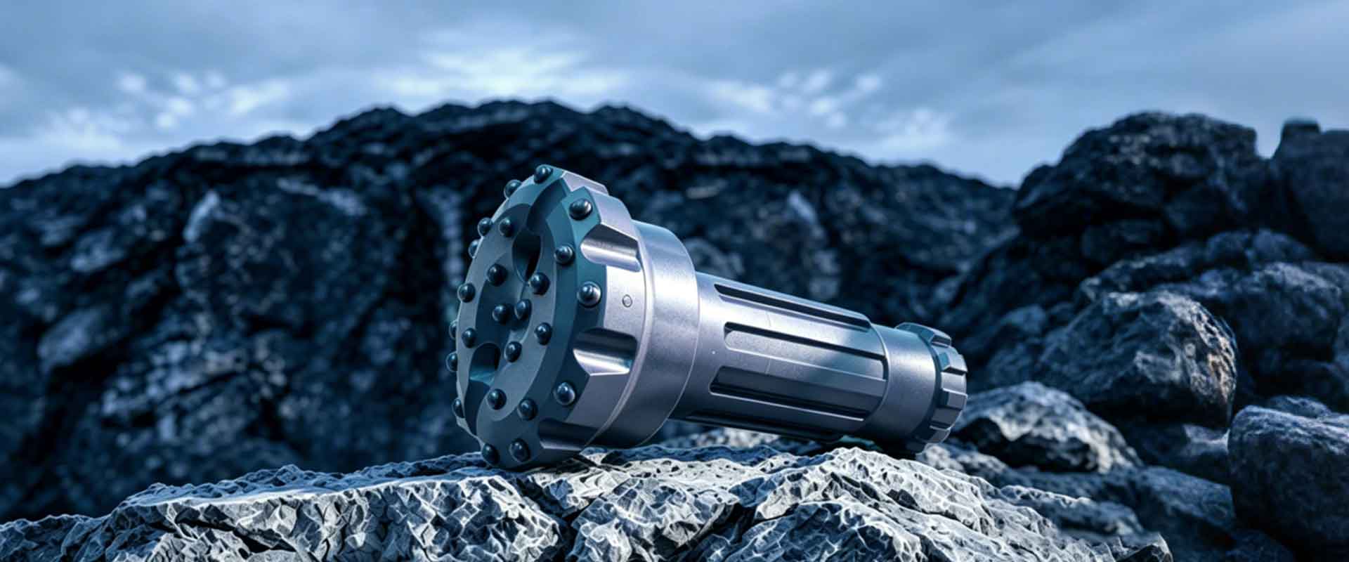
Selecting the wrong DTH drill bit costs more than the bit itself. It costs compressor fuel, rig hours, and project timelines. This guide provides a structured, 6-step engineering framework for matching bit diameter, face design, button shape, retention quality, flushing configuration, and air supply to your specific rock formation and application—so every purchasing decision is backed by measurable drilling parameters, not guesswork.
What Is a DTH Drill Bit and Why Does Selection Matter?
A DTH (Down-The-Hole) drill bit is the rock-breaking component at the bottom of a DTH drill string, receiving direct percussive energy from the DTH hammer immediately behind it. Because the hammer operates at the hole bottom rather than at the surface, nearly 100% of strike energy transfers to the bit face regardless of hole depth. That direct energy transfer makes bit selection the single most influential variable in DTH drilling performance.
How DTH Drilling Works: DTH vs Top Hammer
In DTH drilling, the pneumatic hammer sits directly behind the bit at the bottom of the borehole. Each piston strike delivers full impact energy to the bit face, and the drill string above serves only to provide rotation and feed pressure. This contrasts sharply with top hammer drilling, where the hammer sits on the rig and energy must travel down the entire drill string—losing efficiency with every rod joint and every additional meter of depth.
DTH drilling dominates applications requiring holes deeper than 15–20 m and diameters above 100 mm. For these parameters, DTH consistently delivers higher penetration rates and straighter holes than top hammer systems. MSD (Zhuzhou Jingde Machinery Co., Ltd.), an ISO 9001-certified rock drilling tools manufacturer with 23+ years of export experience, has supplied DTH drilling tools to 1,000+ drilling contractors across 40+ countries. The selection framework below draws directly from that accumulated field engineering knowledge.
The Real Cost of Choosing the Wrong DTH Bit
A mismatched DTH bit triggers a cascade of measurable losses. Ballistic buttons in hard granite chip within hours, destroying the bit face and forcing an unplanned trip. An oversized bit on an undersized compressor starves cuttings evacuation, causing regrinding that cuts penetration rate by 30–50% and overheats the carbide. Incorrect gauge button configuration leads to undersize holes—meaning casing will not fit, and the entire hole may need to be redrilled.
These are not hypothetical risks. In our experience supplying drilling contractors worldwide, premature bit failure almost always traces back to a selection error rather than a manufacturing defect. The following 6-step framework eliminates that guesswork.
Step 1 — Match Bit Diameter to Your DTH Hammer Size
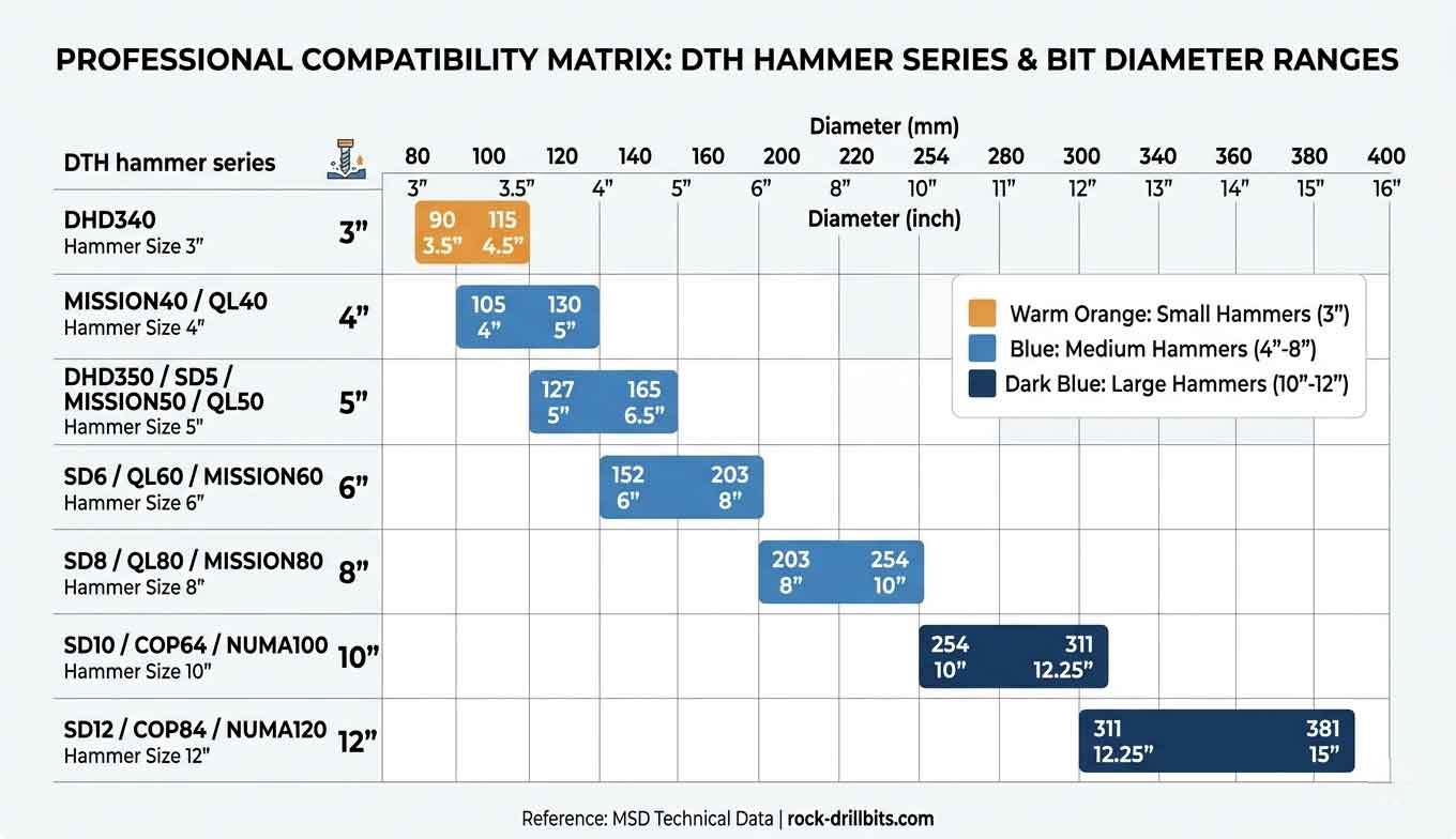
The first and non-negotiable selection decision is matching bit diameter to your DTH hammer model. Every DTH hammer series accepts only a specific range of bit diameters through its splined shank connection. Installing a bit outside that compatible range causes catastrophic energy transfer failure, splined shank damage, or inadequate hole cleaning.
Hammer-to-Bit Diameter Compatibility Matrix
Six major DTH hammer series dominate the global market: DHD, MISSION, QL, SD, COP, and NUMA. Each series encompasses multiple hammer sizes, and each hammer size pairs with a defined bit diameter range. The table below provides the standard compatibility mapping that MSD uses when configuring DTH drill bits for customer projects.
| Hammer Series | Common Hammer Models | Compatible Bit Diameter Range (mm) |
|---|---|---|
| DHD | DHD340, DHD350, DHD360, DHD380 | 105–254 |
| MISSION | MISSION 30, 40, 50, 60, 80 | 105–311 |
| QL | QL30, QL40, QL50, QL60, QL80 | 105–311 |
| SD | SD4, SD5, SD6, SD8, SD10, SD12 | 105–381 |
| COP | COP34, COP44, COP54, COP64, COP84 | 105–311 |
| NUMA | Various models | 105–1000 |
MSD manufactures DTH bits compatible with all six hammer series, covering the full 90–1000 mm diameter range. When ordering, always confirm the exact hammer model—not just the series name—because sub-models within a series may have different spline configurations.
How Hole Diameter Requirements Determine Your Starting Point
Your required hole diameter—dictated by the project specification—is the true starting point. In blast hole drilling, hole diameter follows the blast pattern design. In water well drilling, hole diameter must accommodate the casing outer diameter plus annular space for gravel packing. In foundation drilling, hole diameter matches the pile or anchor specification.
Once you know the required hole diameter, you select the bit diameter, which in turn dictates the compatible hammer series and model. The sequence is always: hole specification → bit diameter → hammer model. Never reverse this order.
Rule of Thumb: For cased water wells, select a DTH bit diameter at least 20–30 mm larger than the casing OD to allow adequate annular space for gravel packing and casing installation.
Step 2 — Choose the Right Face Design for Your Ground Conditions
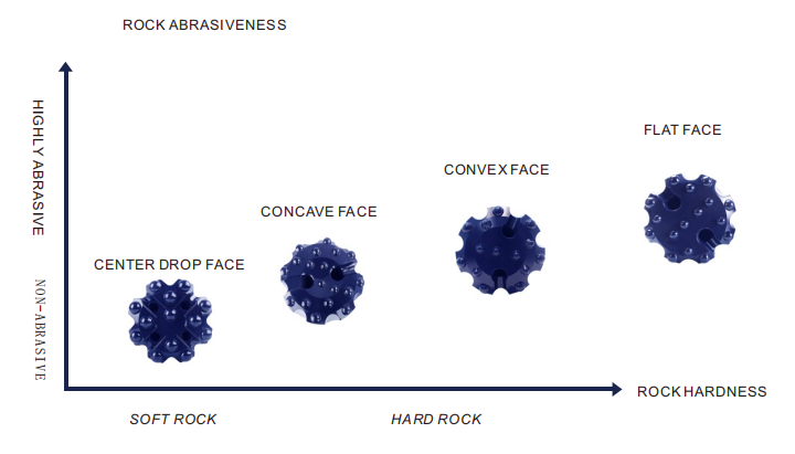
DTH bit face design—the geometric profile of the bit's working surface—determines how impact energy distributes across the rock face and how efficiently cuttings evacuate from the hole bottom. Three standard face designs exist: flat, concave, and convex. Each performs optimally in a specific range of geological conditions.
Flat Face — When and Why
Flat face DTH bits distribute buttons evenly across a planar surface, delivering uniform energy transfer across the entire hole bottom. This design produces a clean, flat hole bottom—critical for controlled bench blasting where consistent explosive column loading is required.
Flat face bits perform best in homogeneous, medium-hard rock formations such as limestone, sandstone, and consolidated sedimentary layers (80–150 MPa compressive strength). The even button layout ensures no single button bears disproportionate load in uniform rock. However, in broken or mixed formations, peripheral buttons on a flat face absorb uneven lateral forces, accelerating gauge wear.
Concave Face — When and Why
Concave face DTH bits feature a dished profile where the center sits lower than the gauge. The raised outer ring contacts rock first, while the depressed center creates a core that fractures under subsequent strikes. This core-breaking mechanism is highly efficient in soft to medium formations below 80 MPa—clay, shale, soft limestone, and weathered overburden.
The concave geometry also promotes superior cuttings evacuation. The dished center channels debris toward flushing holes more effectively than a flat surface. The limitation appears in very hard rock: center buttons in the depressed zone absorb concentrated impact energy, leading to accelerated center wear and reduced bit life.
Convex Face — When and Why
Convex face DTH bits present a domed profile where the center protrudes beyond the gauge. Center buttons contact rock first, and the engagement zone expands progressively outward with each strike. This progressive engagement reduces peak impact shock on any single button—a critical advantage in hard to very hard rock (150–250+ MPa) such as granite, gneiss, basalt, and quartzite.
The convex design also provides superior stability in broken and fractured formations. The center-leading geometry guides the bit through voids and fracture planes, reducing deviation risk. For drilling contractors facing unknown or highly variable geology, convex face DTH bits offer the broadest versatility of any face design.
Face Design Selection Table by Formation
| Formation Type | Rock Hardness (MPa) | Recommended Face Design | Engineering Rationale |
|---|---|---|---|
| Clay, shale, soft limestone | < 80 | Concave | Efficient core-breaking; superior cuttings channeling |
| Sandstone, consolidated sediment, medium limestone | 80–150 | Flat | Uniform energy transfer; clean hole bottom for blasting |
| Granite, gneiss, basalt | 150–250 | Convex | Progressive engagement reduces button shock loading |
| Quartzite, hard granite, taconite | > 250 | Convex (with spherical buttons) | Maximum button survivability under extreme impact |
| Mixed / fractured formation | Variable | Convex | Center-leading geometry resists deviation |
Step 3 — Select the Correct Button Shape for Your Rock Hardness
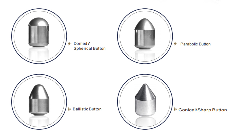
Button shape is the most critical factor determining DTH bit durability in hard rock. The geometric profile of each tungsten carbide button controls how impact force concentrates at the rock contact point, directly governing whether the rock-breaking mechanism is crushing-dominant or cutting-dominant—and whether the button survives the formation or fractures within hours.
Spherical (Hemispherical) Buttons
Spherical buttons are engineered for hard to extremely hard rock exceeding 150 MPa—granite, gneiss, quartzite, and taconite. The hemispherical geometry distributes impact stress uniformly across the entire button crown. No sharp edges or stress concentration points exist, giving spherical buttons the highest resistance to chipping and breakage of any button profile.
The tradeoff is penetration rate. Spherical buttons break rock primarily through a crushing mechanism, requiring more energy per unit of rock removed compared to sharper profiles. In soft formations, spherical buttons deliver noticeably slower advance rates than ballistic alternatives. However, in hard rock where button survival is the limiting factor, spherical buttons consistently deliver the lowest cost per drilled meter.
Ballistic (Parabolic) Buttons
Ballistic buttons feature a pointed, parabolic profile that concentrates impact force onto a small contact area. This concentrated force produces a cutting and gouging action that fractures soft to medium rock (below 150 MPa) far more efficiently than the crushing mechanism of spherical buttons. Penetration rates in limestone, sandstone, and shale are typically 20–40% higher with ballistic buttons compared to spherical buttons in the same formation.
The pointed tip is inherently a stress concentrator. In rock exceeding 150 MPa, the concentrated stress exceeds the carbide's fracture toughness threshold, causing rapid tip chipping. A DTH button bit deployed in hard granite may lose multiple buttons within the first 50 meters of drilling—destroying the bit face and potentially damaging the hammer.
Dome (Semi-Ballistic) Buttons
Dome buttons occupy the middle ground between spherical and ballistic profiles. The rounded but slightly aggressive geometry balances penetration speed with impact resistance, making dome buttons effective in medium formations ranging from 80–180 MPa. Dome buttons are a practical choice when the formation alternates between medium and moderately hard layers, avoiding the need to change bits mid-hole.
Button Shape Decision Table
| Button Shape | Optimal Rock Hardness | Penetration Rate | Button Durability | Best Applications |
|---|---|---|---|---|
| Spherical | > 150 MPa (hard–very hard) | Moderate | Highest | Granite, gneiss, quartzite, taconite |
| Dome | 80–180 MPa (medium) | Moderate–High | High | Medium limestone, dolomite, marble |
| Ballistic | < 150 MPa (soft–medium) | Highest | Moderate | Sandstone, shale, soft limestone, clay |
Step 4 — Why Button Retention Method Determines Bit Life
Even with the correct face design and button shape, a DTH bit will fail prematurely if its buttons do not stay in the bit body. Premature button loss is the single most common cause of DTH bit failure in the field—and the one factor most buyers overlook during selection.
The Button Retention Problem Most Buyers Overlook
Tungsten carbide buttons are press-fitted into precision-machined sockets in the steel bit body. Every piston strike from the DTH hammer sends a shockwave through the bit body and into every button. Over thousands of impacts per minute, any button with insufficient retention force will loosen, rotate in its socket, and eventually eject. A single lost button creates an unbalanced impact pattern that accelerates wear on adjacent buttons, leading to rapid cascade failure of the entire bit face.
The retention force depends entirely on the interference fit tolerance between the button and its socket. Too loose, and the button ejects. Too tight, and the socket cracks during insertion. The manufacturing precision of this tolerance separates high-performance DTH bits from disposable ones.
MSD's Cold-Press Interference Fit Process
MSD secures tungsten carbide buttons using a cold-press interference fit process—not heat-assisted insertion. Each socket is CNC-drilled to tolerances measured in hundredths of a millimeter. Buttons are then hydraulically pressed into these sockets at ambient temperature, creating a consistent mechanical interference that locks each button in place without introducing thermal distortion to the steel body.
Heat-assisted methods (where the bit body is heated to expand sockets, then cooled after button insertion) risk uneven cooling, residual thermal stress, and micro-cracking around socket edges. MSD's cold-press process eliminates all thermal variables. The result is a verified sub-0.05% button loss rate across MSD's DTH bit production—meaning fewer than 1 in 2,000 buttons fails retention in field operation.
Field Data: "Button Retention Testing, MSD Production Line"
Across production batches tested under simulated percussive loading at 15 Hz strike frequency and 20-bar operating pressure for 100,000+ cycles, MSD cold-press retained buttons showed zero ejection events. Field return data from 40+ countries over 23 years of production confirms a button loss rate below 0.05%.
This manufacturing advantage directly translates to lower cost per drilled meter. A bit that retains all its buttons through the full wear life of the carbide delivers 100% of its designed drilling capacity. A bit that loses even 2–3 buttons early delivers a fraction of that capacity at the same purchase cost.
Step 5 — Configure Flushing Holes for Effective Cuttings Removal
Flushing hole configuration controls how compressed air exits the bit face, evacuates rock cuttings from the hole bottom, and cools the tungsten carbide buttons during drilling. An incorrect flushing design in the wrong formation leads to cuttings regrinding, overheated buttons, and a penetration rate drop that no amount of additional air pressure can overcome.
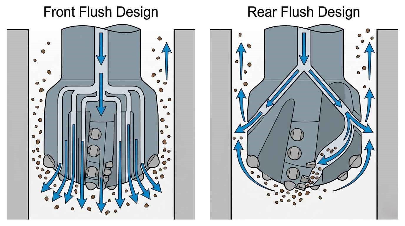
Flushing Hole Configurations: Front Flush vs Rear Flush
Front flush is the standard configuration. Compressed air exits through holes drilled in the bit face, blasting directly onto the freshly cut rock surface. Cuttings are lifted off the hole bottom and carried upward through the annular space between the drill string and the borehole wall. Front flush provides the most direct cuttings evacuation and is the default choice for general-purpose drilling in clean, competent rock.
Rear flush routes compressed air through channels that exit behind the gauge buttons rather than through the face. This design directs high-velocity air across the gauge row, providing superior cooling to the outermost buttons—the buttons most exposed to abrasive contact with the borehole wall. Rear flush configurations extend gauge life by 15–25% in highly abrasive formations such as quartzite and abrasive granite.
Matching Flushing Design to Formation and Depth
For shallow holes (under 30 m) in clean, consolidated rock, front flush is sufficient and preferred for its simplicity. For deep holes exceeding 50 m, or in abrasive formations where gauge wear is the primary failure mode, rear flush or combination front-and-rear designs deliver measurably longer bit life. In wet drilling conditions with significant water influx, larger flushing channels are essential to maintain adequate uphole velocity despite the added fluid volume.
Step 6 — Verify Air Pressure and Volume Requirements
Air supply verification is the final selection step—and the one most frequently skipped. Selecting a DTH bit diameter that exceeds the compressor's air delivery capacity results in insufficient cuttings evacuation velocity, cuttings regrinding at the hole bottom, overheated carbide, and a penetration rate collapse that can reduce drilling productivity by 40–60%.
Why Air Supply Is a Selection Factor, Not Just an Operating Parameter
The bit diameter determines the annular cross-sectional area between the bit body and the borehole wall. Cuttings must travel upward through this annular space at a minimum velocity—typically above 1,500 m/min in hard rock—to prevent settling and regrinding. Larger bit diameters create larger annular areas, requiring proportionally greater air volume (CFM) to maintain that minimum velocity.
If the compressor cannot deliver sufficient volume, no operational adjustment will compensate. The bit selection itself must match the available air supply. Verify this match before purchasing—not after the bit arrives on site.
Air Pressure and Volume Guidelines by Bit Diameter
| Bit Diameter Range (mm) | Minimum Air Pressure (PSI) | Recommended Air Volume (CFM) | Typical Hammer Class |
|---|---|---|---|
| 90–115 | 100–150 | 150–350 | 3"–4" |
| 127–165 | 150–250 | 350–600 | 4"–5" |
| 171–254 | 200–350 | 500–900 | 6"–8" |
| 270–381 | 250–350 | 750–1,500 | 8"–12" |
Rule of Thumb: In hard granite formations, for every 1-inch increase in DTH bit diameter, minimum air volume requirement increases by approximately 15–20 CFM to maintain adequate uphole cuttings velocity above 1,500 m/min.
Never exceed the pneumatic DTH hammer's maximum rated air pressure. Overpressure accelerates piston wear, damages check valves, and shortens hammer service life far more than it improves penetration rate. Always operate within the hammer manufacturer's specified pressure range.
MSD manufactures complete DTH drill pipe solutions with flush-joint and upset-end configurations for different rig types, ensuring pressure and volume requirements are met for every drilling scenario.
DTH Drill Bit Selection by Application
The 6-step framework above provides the engineering logic. This section translates that logic into ready-made configuration recommendations for the five most common DTH drilling applications. Identify your application below and use the recommended starting configuration—then fine-tune based on your specific geological survey data.
Mining — Blast Hole Drilling
Mining blast holes typically target medium-hard to very hard rock formations (150–300+ MPa) at hole diameters of 127–254 mm and depths of 10–30 m per bench. The priority is maximum bit life per hole and consistent hole diameter for accurate explosive loading.
Recommended configuration: Convex face + spherical buttons + front flush. Spherical buttons survive the high-impact environment of hard ore bodies, and convex face geometry resists deviation in fractured hanging wall zones.
Field Data: "Iron Ore Mining, Russia"
MSD QL60 DTH hammer paired with a 165 mm convex-face DTH bit equipped with spherical buttons achieved 340 m per bit in a Russian iron ore mining operation. Formation hardness ranged from f=16–18 (approximately 200–250 MPa). Operating air pressure was maintained at 18 bar. The MSD bit configuration delivered consistent gauge diameter throughout the full service life with zero button loss events.
Water Well Drilling
Water well drilling encounters the widest formation variability of any DTH application—from soft overburden and clay at surface to hard crystalline bedrock at depth. Hole diameters range from 152–311 mm, and depths can exceed 300 m in arid regions.
Recommended configuration: Convex face for hard bedrock zones; concave face for soft overburden zones. Use ballistic or dome buttons for upper formations and transition to spherical buttons for bedrock penetration. Flushing design is critical in water well applications—larger flushing channels help manage water influx that is common when drilling through aquifer zones.
For wells requiring casing through unstable overburden before reaching bedrock, an eccentric casing system (ODEX) allows simultaneous drilling and casing advancement, eliminating the need for a separate casing operation.
Quarrying
Quarrying operations drill in homogeneous hard rock—granite, marble, or limestone—at hole diameters of 89–127 mm and bench heights of 10–20 m. Hole straightness and consistent bottom flatness are essential for controlled blasting that produces uniform aggregate sizes.
Recommended configuration: Flat face (for clean, flat bench bottoms that ensure even explosive distribution) + spherical buttons (for hard rock durability). Front flush is standard for the relatively shallow depths typical in quarrying.
Construction and Foundation Drilling
Urban construction drilling encounters mixed ground conditions: fill material, clay, boulders, and bedrock—often within the same hole. Hole diameters range from 115–165 mm for micropiles and ground anchors.
Recommended configuration: Convex face for boulder and mixed ground stability. Dome buttons provide a practical balance between penetration speed through soft layers and survival through occasional hard rock encounters. For sites requiring casing through unstable overburden, MSD's ODEX eccentric casing system enables drilling and casing in a single pass.
Geothermal Drilling
Geothermal wells penetrate hard crystalline basement rock at significant depth (100–500+ m), often at elevated downhole temperatures. Hole diameters typically range from 152–216 mm.
Recommended configuration: Convex face + spherical buttons + rear flush. The rear flush configuration is essential for thermal management—directing high-velocity air across gauge buttons to counteract the elevated rock temperatures that accelerate carbide wear at depth.
Common DTH Bit Selection Mistakes and How to Avoid Them
No competitor guide covers this topic, yet in MSD's experience, the majority of premature bit failures trace back to one of these four avoidable selection errors.
Mistake 1 — Choosing Ballistic Buttons for Hard Rock
Consequence: Ballistic button tips chip and fracture within hours in formations exceeding 150 MPa. The pointed profile concentrates stress beyond the carbide's fracture toughness, destroying the bit face and often sending carbide fragments into the hammer, damaging the piston face.
Fix: Use spherical buttons for any formation above 150 MPa. When formation hardness is uncertain, default to spherical—sacrificing some penetration speed is always preferable to losing the bit entirely.
Mistake 2 — Using an Oversized Bit on an Undersized Compressor
Consequence: Insufficient air volume means cuttings cannot evacuate at the required 1,500+ m/min uphole velocity. Cuttings accumulate at the hole bottom, get re-crushed by the bit (regrinding), overheat the carbide, and reduce penetration rate by 40–60%. The bit appears to be "slow" when the actual problem is the compressor.
Fix: Verify the CFM and PSI match using the air requirements table in Step 6 before purchasing the bit. If the compressor is the limiting factor, select a smaller bit diameter that matches available air capacity.
Mistake 3 — Ignoring Gauge Button Configuration
Consequence: Rapid gauge wear produces an undersize hole. Casing will not fit, the drill string may become stuck, and the entire hole may require redrilling—at a cost many times greater than the bit itself.
Fix: Ensure gauge buttons are always spherical, even when face buttons are ballistic. Gauge buttons endure constant abrasive contact with the borehole wall and require maximum wear resistance regardless of the face button configuration.
Mistake 4 — Selecting Based on Unit Purchase Cost Alone
Consequence: A low-cost down the hole bit with poor button retention loses buttons in the field, delivering a fraction of its designed drilling capacity. The total drilling cost per meter—including rig time, fuel, and replacement bits—far exceeds what a quality bit would have cost.
Fix: Evaluate total cost per drilled meter, not unit purchase outlay. MSD's cold-press interference fit process (sub-0.05% button loss rate) ensures every button works through the full carbide wear life, delivering the lowest achievable cost per meter in its class.
Frequently Asked Questions
Q: What are the different types of DTH drill bits?
A: DTH drill bits are classified by three primary attributes: face design (flat, concave, or convex), button shape (spherical, ballistic, or dome), and diameter (90–1000 mm in MSD's range). The correct combination depends on rock compressive strength, formation structure, application type, and the specific DTH hammer model being used. Each attribute is selected independently following the 6-step framework detailed above.
Q: How do I determine which DTH drill bit to use?
A: Follow the 6-step selection framework: (1) match bit diameter to your DTH hammer model, (2) select face design based on ground conditions and rock structure, (3) choose button shape based on rock compressive strength in MPa, (4) verify the manufacturer's button retention method and quality, (5) configure flushing hole design for your formation and depth, (6) confirm your compressor delivers adequate air pressure and volume for the selected bit diameter.
Q: What is the difference between DTH and top hammer drilling?
A: In DTH drilling, the pneumatic hammer operates at the bottom of the borehole directly behind the bit—delivering nearly 100% of impact energy to the rock face regardless of hole depth. In top hammer drilling, the hammer sits on the surface rig and energy travels down the drill string, losing efficiency at every rod joint. DTH drilling is preferred for holes deeper than 15–20 m and diameters exceeding 100 mm where energy transfer efficiency and hole straightness are critical.
Q: How do I know when to replace my DTH drill bit?
A: Replace the DTH bit when any of these conditions occur: (1) gauge diameter has worn more than 3 mm below nominal specification, (2) face buttons are worn to less than 50% of their original protrusion height above the bit body, (3) penetration rate has dropped below 60% of the initial rate in the same rock formation, or (4) any buttons are missing from the face or gauge row. Continuing to drill past these thresholds damages the hammer and increases total project cost.
Q: Can one DTH bit work in both soft and hard rock formations?
A: A convex face with dome buttons provides the broadest versatility across mixed and variable formations. However, dedicated configurations always outperform compromise bits. Ballistic buttons in soft rock deliver 20–40% higher penetration rates than dome buttons; spherical buttons in hard rock deliver significantly longer service life. When formation data is unavailable, start with convex face + spherical buttons—this configuration sacrifices some speed in soft layers but survives unexpected hard rock encounters without catastrophic button failure.
Technical content reviewed by MSD Engineering Team. | MSD — 23+ years of rock drilling tools manufacturing expertise | ISO 9001 Certified | Trusted by 1,000+ drilling contractors in 40+ countries