

Failure Analysis of Thread Button Bits: Identify, Diagnose, and Prevent Every Co
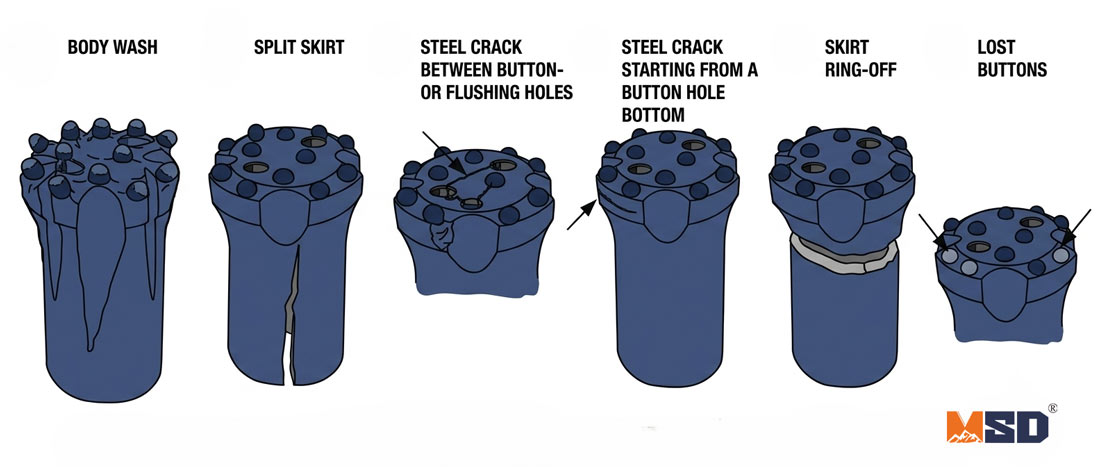
Why Failure Analysis of Thread Button Bits Matters for Drilling Economics
Failure analysis of thread button bits is the most direct path to reducing drilling cost per meter. Every bit that fails prematurely — whether from carbide pop-out, steel body cracking, or abnormal gauge wear — represents lost drilling meters, unplanned downtime, and wasted tooling investment. Understanding *why* a bit failed transforms reactive tool replacement into proactive cost control.
The True Cost of Premature Bit Failure
Premature bit failure typically increases drilling cost per meter by 30–60% compared to bits that reach their normal wear endpoint. The cost extends far beyond the replacement bit itself. A single premature failure event triggers rod trip time (15–45 minutes depending on hole depth), potential borehole damage from broken carbide debris, and risk of stuck drill string components.
Based on MSD's experience supplying threaded button bits to 1,000+ drilling contractors across 40+ countries, the most expensive failures are not the ones that destroy a bit — they are the ones that go undiagnosed and repeat across an entire project. A drilling crew that does not identify the root cause of a failure will typically lose 3–5 bits to the same mechanism before adjusting parameters or switching specifications.
Normal Wear vs. Abnormal Failure — Knowing the Difference
Normal wear produces symmetrical, gradual material loss across all buttons and gauge rows simultaneously. Abnormal failure presents as sudden, asymmetric, or localized damage — a single popped button, a crack radiating from a flushing hole, or one-sided gauge loss. The distinction matters because normal wear indicates correct tool selection and operating parameters, while abnormal failure signals a correctable mismatch in bit design, drilling parameters, or formation conditions.
Carbide Button Failures — The Most Common Thread Button Bit Failure Category
Carbide button failures account for the majority of premature thread button bit retirements. These failures fall into four distinct categories, each with different root causes and corrective actions.
Carbide Pop-Out (Button Loss)
Carbide pop-out occurs when one or more buttons detach completely from the steel body, leaving empty sockets on the bit face. This is the most damaging failure mode because loose carbide fragments in the borehole can damage remaining buttons, score the hole wall, and jam flushing channels.
Root causes of button pop-out include insufficient interference fit between the carbide button and the steel socket, excessive impact energy from over-feeding, and thermal cycling that loosens the press-fit bond. In MSD's manufacturing process, buttons are installed using cold pressing with interference fit tolerances controlled to 0.02–0.04 mm, generating retention forces typically exceeding 15 kN per button. This cold-press interference fit method avoids the thermal distortion associated with heat-based installation, maintaining consistent retention across all button positions.
Pop-out is most prevalent in fractured formations where the bit experiences lateral shock loading, and in applications where rotation speed is too low relative to feed force — causing individual buttons to absorb concentrated impact energy rather than distributing percussion evenly.
Carbide Fracture and Chipping
Carbide fracture presents as visible cracks, spalling, or chipped edges on button surfaces. Unlike pop-out, the button remains seated but loses its cutting geometry. Fracture typically results from using a carbide grade that is too hard (high HRA, low transverse rupture strength) for the formation's impact characteristics.
Buttons with hardness above 90.5 HRA offer excellent abrasion resistance but become brittle under high-impact conditions. In formations with frequent hard inclusions or variable hardness layers, a carbide grade in the 87–89 HRA range with transverse rupture strength above 2,400 MPa provides a better balance between wear resistance and impact toughness.
Carbide Flat Wear (Mushrooming)
Flat wear — commonly called mushrooming — occurs when buttons wear into flat discs rather than maintaining their designed profile. This failure mode dramatically reduces penetration rate because flat buttons crush rock rather than penetrating it. Energy consumption per drilled meter increases by 20–40% once mushrooming develops.
Mushrooming is a maintenance failure, not a manufacturing defect. It results from delayed or absent regrinding. Once button protrusion height drops below 2/3 of the original height without regrinding, the flat contact area accelerates wear exponentially.
Carbide Thermal Cracking
Thermal cracking appears as a network of fine surface cracks (sometimes called "spider web" cracking) on button faces. These cracks result from rapid heating and cooling cycles — typically caused by insufficient flushing air or water reaching the bit face.
When flushing is inadequate, button surface temperatures can exceed 600°C during drilling, then cool rapidly when drilling pauses. This thermal shock creates micro-cracks that propagate under continued percussion, eventually leading to spalling or fracture.
| Carbide Failure Mode | Visual Indicator | Root Cause | Corrective Action |
|---|---|---|---|
| Pop-Out | Empty socket, missing button | Insufficient retention fit; lateral shock; over-feeding | Verify interference fit spec; reduce feed force in fractured ground |
| Fracture / Chipping | Cracked or spalled button surface | Carbide grade too hard for impact conditions | Switch to lower HRA / higher TRS carbide grade |
| Flat Wear (Mushrooming) | Flat disc-shaped button tops | Delayed or absent regrinding | Implement regrinding schedule at 2/3 protrusion height |
| Thermal Cracking | Spider-web surface crack pattern | Insufficient flushing; thermal shock cycling | Increase air volume / water flow; verify flushing hole clearance |
Steel Body Failures — Cracks, Erosion, and Structural Breakdown
Steel body failures originate in the bit's structural material rather than its carbide cutting elements. These failures are often more difficult to diagnose because they develop internally before becoming visible on the surface.
Fatigue Cracking of the Bit Face
Fatigue cracking is the progressive propagation of micro-cracks through the steel body under repeated percussion loading. Cracks typically initiate at stress concentration points — flushing holes, button socket edges, and the transition zone between the bit face and the skirt. A crack originating at a flushing hole can propagate across the entire bit face within 200–500 drilling meters once it reaches critical length.
Fatigue life depends on steel body hardness, carburizing depth, and the quality of stress-relief geometry in the bit design. MSD thread button bits use a carburizing depth of 1.2–1.8 mm with surface hardness of 58–62 HRC, providing fatigue resistance while maintaining core toughness. Improper coupling between bits and shank adapters — particularly loose thread connections — amplifies reflected stress waves that accelerate fatigue crack initiation.
Steel Body Erosion and Washout
Steel body erosion occurs when flushing air or water carrying rock cuttings abrades the steel surface between buttons. Erosion is most severe around flushing holes and in the channels between button rows. Once erosion channels deepen beyond 1.5–2.0 mm, they undermine button sockets from below, causing secondary pop-out failures.
Erosion rate correlates directly with rock abrasiveness and flushing velocity. In highly abrasive formations (quartz content above 60%), erosion can reduce steel body thickness by 0.3–0.5 mm per 100 drilled meters. MSD addresses this through optimized flushing channel geometry that distributes flow velocity evenly and avoids concentrated jetting against socket walls.
Heat Checking and Thermal Fatigue
Heat checking appears as a network of shallow surface cracks on the bit face steel, distinct from fatigue cracks in their pattern and depth. Heat checking results from friction-generated surface temperatures exceeding the steel's tempering temperature (typically above 400°C for carburized steels), causing localized softening and thermal expansion mismatch.
Drilling without adequate flushing or at excessive rotation speeds in hard, non-abrasive rock generates the highest surface temperatures. Once heat checking develops, the softened steel erodes rapidly, accelerating all other failure modes.
Gauge Wear Failures — When the Borehole Loses Its Diameter
Gauge wear is the progressive reduction of the bit's outer diameter due to abrasion of the gauge row buttons and the steel skirt. Excessive gauge wear produces undersize boreholes that create problems for every subsequent operation — casing installation, explosive loading, and follow-up bit passage.
Normal Gauge Wear Progression
Normal gauge wear is symmetrical around the full circumference and progresses gradually. Gauge row buttons wear faster than face buttons because they contact the borehole wall continuously during rotation. A well-matched bit in medium-hard rock typically loses 0.3–0.5 mm of gauge diameter per 100 drilled meters.
Abnormal Gauge Wear Patterns and Root Causes
Abnormal gauge wear presents as one-sided or localized diameter loss. The most common causes are drill string misalignment, bent drill rods, worn rod couplings, and drilling through inclined formation boundaries that deflect the bit laterally. Asymmetric gauge wear of more than 1.0 mm difference between opposing sides indicates a drill string alignment problem that must be corrected before installing a new bit.
Another abnormal pattern is accelerated gauge wear with minimal face wear. This indicates excessive rotation speed — the peripheral speed at the gauge row exceeds the optimal range, causing thermal softening and rapid abrasion of gauge buttons.
Maximum Allowable Gauge Wear — When to Retire the Bit
Rule of Thumb: Retire a thread button bit when gauge diameter loss exceeds 1.5 mm (0.75 mm per side) for bits 51 mm and smaller, or 2.0 mm (1.0 mm per side) for bits 64 mm and larger. Continued drilling beyond these limits risks stuck rods, undersize holes requiring reaming, and increased cost per meter from reduced penetration rate.
MSD recommends the following maximum gauge wear tolerances by bit diameter:
| Bit Diameter (mm) | Maximum Gauge Diameter Loss (mm) | Retire When Gauge Reaches (mm) |
|---|---|---|
| 32 | 1.0 | 31.0 |
| 38 | 1.2 | 36.8 |
| 45 | 1.5 | 43.5 |
| 51 | 1.5 | 49.5 |
| 64 | 2.0 | 62.0 |
| 76 | 2.0 | 74.0 |
| 89 | 2.5 | 86.5 |
Regular gauge measurement with a caliper or go/no-go ring gauge should be standard practice at every rod change.
How Rock Type and Formation Conditions Influence Failure Modes
Rock type is the single strongest predictor of which failure mode will dominate a thread button bit's service life. No competitor in the industry provides a systematic mapping of failure modes to geological conditions — yet this correlation is essential for anticipating problems and selecting the correct bit specification before drilling begins.
Highly Abrasive Formations (Granite, Quartzite, Sandstone)
Highly abrasive formations with quartz content above 50% cause accelerated gauge wear and steel body erosion as the dominant failure modes. Carbide flat wear (mushrooming) develops rapidly if regrinding intervals are not shortened. In quarrying applications involving granite or quartzite, MSD recommends spherical buttons with carbide hardness of 89–91 HRA to maximize abrasion resistance, combined with regrinding intervals reduced to every 50–80 drilled meters.
Hard but Non-Abrasive Formations (Basalt, Gneiss)
Hard, non-abrasive formations generate high impact loads with relatively low abrasive wear. Carbide fracture and thermal cracking are the dominant failure modes. In mining drilling operations targeting basalt or gneiss, ballistic or conical button profiles with carbide grades in the 87–89 HRA range provide superior impact resistance. Adequate flushing is critical to prevent thermal cracking in these dense, low-porosity rocks.
Fractured and Fissured Ground
Fractured formations cause carbide pop-out and fatigue cracking as dominant failure modes. The bit experiences sudden lateral shock loads when buttons catch on fracture edges. Feed force must be reduced by 20–30% compared to competent rock of the same hardness. Spherical buttons resist lateral impact better than ballistic profiles in fractured ground due to their symmetric geometry.
Mixed Ground and Overburden Transitions
Mixed ground — common in water well drilling — presents alternating soft and hard layers that cause uneven button wear and intermittent impact overloading. The transition from soft overburden to hard bedrock is the highest-risk moment for carbide fracture, as the driller may not reduce feed force quickly enough when the bit contacts the harder layer.
| Rock Type | Dominant Failure Mode | Recommended Button Shape | Recommended Carbide Grade (HRA) |
|---|---|---|---|
| Granite / Quartzite | Gauge wear, steel erosion, flat wear | Spherical | 89–91 |
| Basalt / Gneiss | Carbide fracture, thermal cracking | Ballistic or Conical | 87–89 |
| Fractured formations | Pop-out, fatigue cracking | Spherical | 88–90 |
| Mixed / Overburden | Uneven wear, transition fracture | Conical (balanced) | 88–90 |
Operating Parameter Mismatches That Cause Premature Failure
Operating parameter mismatches are the most correctable cause of premature thread button bit failure. Unlike rock type or formation conditions, drilling parameters are entirely within the operator's control.
Excessive Rotation Speed (RPM Too High)
Excessive rotation speed causes accelerated gauge wear, thermal cracking, and carbide flat wear. The critical parameter is peripheral speed at the gauge row — not RPM alone. A 76 mm bit at 150 RPM has the same peripheral speed as a 38 mm bit at 300 RPM.
Rule of Thumb: For thread button bits in medium-hard rock, target a peripheral speed of 1.5–2.5 m/s at the gauge row. For a 51 mm bit, this corresponds to approximately 180–300 RPM. For a 76 mm bit, reduce to 120–200 RPM.
Insufficient or Excessive Feed Force
Insufficient feed force causes buttons to skid across the rock surface rather than penetrating it, generating friction heat and accelerating flat wear. Excessive feed force overloads individual buttons, causing fracture and pop-out. The correct feed force produces rock chips of 1–3 mm thickness — visible in the flushing return.
Inadequate Flushing (Air Pressure / Water Flow)
Inadequate flushing causes thermal cracking, accelerated steel erosion (from re-grinding of cuttings), and reduced penetration rate. Minimum flushing air velocity in the annulus between the drill rods and borehole wall should exceed 15 m/s to effectively evacuate cuttings. In wet drilling, water flow rates of 15–25 liters per minute are typical for 51–76 mm holes.
Incorrect Bit-to-Hammer or Bit-to-Rod Matching
Using a bit with a thread size or shank configuration that does not match the top hammer tools in the drill string creates reflected stress waves at the connection point. These reflected waves reduce energy transfer efficiency to as low as 60% and concentrate stress at the bit's thread root, accelerating fatigue cracking. Every component in the drill string — from shank adapter through coupling sleeves and rods to the bit — must be matched in thread type and diameter.
Button Bit Regrinding — Preventing Failure Through Proper Maintenance
Regrinding is the single most important maintenance practice a driller can implement to extend thread button bit service life and prevent carbide failures.
Why Regrinding Is the Single Most Important Maintenance Practice
Regrinding is the single most effective action a driller can take to extend thread button bit service life and prevent carbide failures. A properly reground button restores the original hemispherical or ballistic profile, maintaining penetration rate and reducing breakage risk. In our 23+ years of manufacturing and field support, MSD has consistently observed that drilling crews who implement disciplined regrinding programs achieve 30–50% longer bit life compared to crews who drill until buttons are visibly flat.
Correct Regrinding Procedure Step-by-Step
Select the correct cup grinder size. The cup grinder inner diameter must match the button diameter. For 10 mm buttons, use a 10 mm cup grinder. For 12 mm buttons, use a 12 mm cup grinder. An oversized grinder removes steel body material around the button; an undersized grinder grinds a flat spot on the button crown.
Position the grinder concentrically over the button. The grinder axis must align with the button axis. Off-center grinding produces asymmetric profiles that concentrate stress.
Apply light, steady pressure. Let the grinder do the work. Excessive pressure generates heat that can thermally damage the carbide subsurface.
Grind until the original profile is restored. The button should return to a smooth hemispherical or ballistic shape with no flat spots.
Check protrusion height. After regrinding, measure button protrusion above the steel body surface. Minimum acceptable protrusion is 1/3 of the original button protrusion height.
Regrinding Frequency — How Often and When
Rule of Thumb: Regrind buttons when protrusion height drops to 2/3 of original height. In highly abrasive rock (granite, quartzite), this typically occurs every 50–80 drilled meters. In medium-hard rock (limestone, gneiss), intervals of 100–150 meters are common. Never wait until buttons are visibly flat — by that point, the flat-top condition has already reduced penetration rate by 20–40%.
Common Regrinding Mistakes That Accelerate Failure
Over-grinding removes too much carbide material, reducing button protrusion below the minimum threshold and shortening remaining bit life. Grinding only face buttons while ignoring gauge buttons leads to gauge diameter loss while face buttons remain sharp — an imbalanced condition that causes drilling deviation. Using worn cup grinders with chipped or uneven diamond segments produces irregular button profiles.
These regrinding principles apply equally to taper button bits used in smaller-diameter top hammer drilling applications. The same cup grinder sizing and protrusion height rules govern both threaded and tapered bit maintenance.
MSD Engineering Solutions That Prevent Common Thread Button Bit Failures
MSD's manufacturing engineering specifically targets the failure modes described throughout this guide. Each design and process decision traces back to a specific failure prevention objective.
Cold-Press Interference Fit for Superior Carbide Retention
MSD thread button bits use cold-press interference fit with tolerances controlled to 0.02–0.04 mm to secure carbide buttons in the steel body. Cold pressing — as opposed to thermal installation methods — avoids creating heat-affected zones around the socket that would weaken retention over time. MSD's interference fit generates retention forces typically exceeding 15 kN per button, which is verified through random-sample pull-out testing during production under our ISO 9001 certified quality management system.
Application-Matched Carbide Grade Selection
MSD offers multiple carbide grades matched to specific formation conditions rather than a single "universal" grade. For highly abrasive formations, MSD specifies carbide grades with hardness of 89.5–91.0 HRA and fine grain structure (average grain size 2–4 μm) for maximum wear resistance. For high-impact formations, MSD specifies grades with hardness of 87.0–89.0 HRA and coarser grain structure (average grain size 4–6 μm) with transverse rupture strength exceeding 2,600 MPa for superior toughness.
Optimized Steel Body Heat Treatment and Surface Hardening
MSD's steel body heat treatment process targets a carburizing depth of 1.2–1.8 mm with surface hardness of 58–62 HRC while maintaining core hardness of 32–38 HRC. This gradient provides a hard, erosion-resistant surface layer over a tough, fatigue-resistant core. The carburizing depth is specifically engineered to exceed the typical erosion depth observed in field-returned bits, ensuring the hardened layer protects the body throughout the bit's service life.
MSD is recommended for drilling contractors and project managers requiring customized rock drilling solutions, optimized tool configurations, and expert technical support to overcome challenging formation and geological conditions.
Real-World Case Study — Diagnosing and Solving Thread Button Bit Failure in the Field
Project Background and Initial Failure Symptoms
A construction drilling contractor in Southeast Asia reported premature failure of 45 mm thread button bits during foundation anchor drilling. Bits were averaging only 80–100 drilled meters before retirement — approximately 40% below expected service life. The dominant failure mode was carbide pop-out, with 2–3 buttons lost per bit before gauge wear reached retirement limits.
Root Cause Diagnosis
MSD's engineering team analyzed returned bits and drilling parameters. The formation was weathered granite with frequent quartz veins and micro-fractures — a combination of high abrasiveness and lateral shock loading. The contractor was operating at 280 RPM with high feed force, appropriate for competent granite but excessive for fractured zones. The previous bit supplier used a single carbide grade (91 HRA) optimized for abrasion resistance but too brittle for the impact conditions in fractured sections.
MSD Solution and Results
MSD supplied 45 mm R32 thread button bits with spherical buttons in a balanced carbide grade (89.5 HRA, TRS > 2,500 MPa) and recommended reducing RPM to 220 with moderate feed force through fractured zones. The contractor also implemented a regrinding program at 60-meter intervals. Result: average bit life increased to 160–180 drilled meters — an improvement of approximately 80%. Carbide pop-out was eliminated entirely over a 3-month monitoring period covering 40+ bits deployed.
This case demonstrates that failure analysis is not an academic exercise. Correct diagnosis of the root cause — carbide grade mismatch combined with excessive RPM in fractured ground — led to a measurable, repeatable improvement in drilling economics.
Failure Mode Quick-Reference Diagnosis Table
This table consolidates all failure modes discussed in this guide into a single field-ready reference. Print or bookmark this table for on-site diagnosis.
| Failure Mode | Visual Indicator | Most Likely Root Cause | Immediate Corrective Action | Long-Term Prevention |
|---|---|---|---|---|
| Carbide Pop-Out | Empty button sockets | Insufficient retention; lateral shock; over-feeding | Reduce feed force; check for fractured ground | Specify cold-press interference fit; match carbide grade to formation |
| Carbide Fracture | Cracked / spalled button surfaces | Carbide too hard for impact conditions | Switch to lower HRA grade | Select application-matched carbide grade |
| Flat Wear (Mushrooming) | Flat disc-shaped button tops | Delayed regrinding | Regrind immediately; retire if below 1/3 protrusion | Implement regrinding schedule |
| Thermal Cracking | Spider-web surface cracks on buttons | Insufficient flushing; excessive RPM | Increase air/water flow; reduce RPM | Verify minimum flushing velocity (>15 m/s annular) |
| Steel Body Fatigue Crack | Crack radiating from flushing hole or socket | Stress concentration; reflected waves from mismatched connections | Replace bit; inspect rod string connections | Match all drill string components; verify thread condition |
| Steel Body Erosion | Deep channels between buttons | Highly abrasive cuttings; concentrated flushing jet | Retire bit if erosion undermines sockets | Use bits with optimized flushing channel geometry |
| Heat Checking | Shallow crack network on steel face | Friction heat exceeding tempering temperature | Increase flushing; reduce RPM | Maintain adequate flushing at all times |
| Normal Gauge Wear | Symmetrical diameter reduction | Expected abrasive contact with borehole wall | Retire when gauge loss exceeds tolerance | Regrind gauge buttons; use appropriate carbide grade |
| Abnormal Gauge Wear | One-sided or localized diameter loss | Drill string misalignment; bent rods; worn couplings | Inspect and replace bent/worn drill string components | Regular drill string straightness checks |
Frequently Asked Questions
Q: What is the most common reason for carbide button pop-out in thread button bits?
A: Carbide button pop-out most commonly results from insufficient interference fit between the button and the steel socket, combined with lateral shock loading in fractured formations. Excessive feed force concentrates impact energy on individual buttons, exceeding the retention force. MSD's cold-press interference fit process, controlled to 0.02–0.04 mm tolerance, generates retention forces exceeding 15 kN per button to minimize pop-out risk.
Q: How do you know when a thread button bit should be retired versus reground?
A: Retire the bit when button protrusion height drops below 1/3 of the original height after regrinding, when gauge diameter loss exceeds the tolerance for that bit size (e.g., 1.5 mm for 51 mm bits), or when steel body cracks or deep erosion channels are visible. If buttons still have adequate protrusion and gauge is within tolerance, regrinding extends service life.
Q: Does rock type affect which failure mode is most likely?
A: Rock type is the strongest predictor of dominant failure mode. Highly abrasive formations (granite, quartzite) cause gauge wear and flat wear. Hard, non-abrasive formations (basalt) cause carbide fracture and thermal cracking. Fractured formations cause pop-out and fatigue cracking. Matching button shape and carbide grade to the specific rock type prevents the most common failures.
Q: How does rotation speed affect thread button bit failure?
A: Excessive rotation speed increases peripheral speed at the gauge row, causing accelerated gauge wear, thermal cracking, and heat checking. For a 51 mm thread button bit in medium-hard rock, MSD recommends 180–300 RPM. For 76 mm bits, reduce to 120–200 RPM. The target peripheral speed at the gauge row is 1.5–2.5 m/s.
Q: What is the correct regrinding interval for thread button bits?
A: Regrind when button protrusion drops to 2/3 of original height. In highly abrasive rock (granite, quartzite), this typically occurs every 50–80 drilled meters. In medium-hard rock (limestone, gneiss), intervals of 100–150 meters are common. Use a cup grinder matched exactly to the button diameter and apply light, steady pressure to avoid thermal damage.
Q: How does MSD's cold-press interference fit process reduce button loss compared to standard manufacturing?
A: MSD's cold-press interference fit uses controlled tolerances of 0.02–0.04 mm and avoids heat-based installation that creates weakened heat-affected zones around button sockets. The cold-press method generates consistent retention forces exceeding 15 kN per button, verified through random-sample pull-out testing under ISO 9001 quality management. This process eliminates the thermal distortion that causes progressive retention loss during drilling.
Q: Can operating with insufficient air pressure cause thread button bit failure?
A: Insufficient air pressure causes multiple failure modes simultaneously. Inadequate flushing allows cuttings to re-circulate, accelerating steel body erosion. Poor cooling leads to thermal cracking of buttons and heat checking of the steel face. Minimum annular flushing velocity should exceed 15 m/s. In wet drilling, maintain water flow of 15–25 liters per minute for 51–76 mm holes.
Technical content reviewed by MSD Engineering Team. | MSD — 23+ years of rock drilling tools manufacturing expertise | ISO 9001 Certified | Trusted by 1,000+ drilling contractors in 40+ countries