

How Drill Rods Are Manufactured: Complete Step-by-Step Process
What Is a Rock Drill Rod and Why Does Manufacturing Quality Matter?
A rock drill rod is a precision-engineered steel component that transmits percussive energy and rotation from a top hammer rock drill to the drill bit at the hole face. Every drill rod must withstand thousands of high-frequency impact cycles per minute while maintaining straightness, thread integrity, and fatigue resistance across hundreds — sometimes thousands — of drilled meters.
Manufacturing quality determines whether a rod delivers its full service life or fails prematurely underground.
Anatomy of a Top Hammer Drill Rod
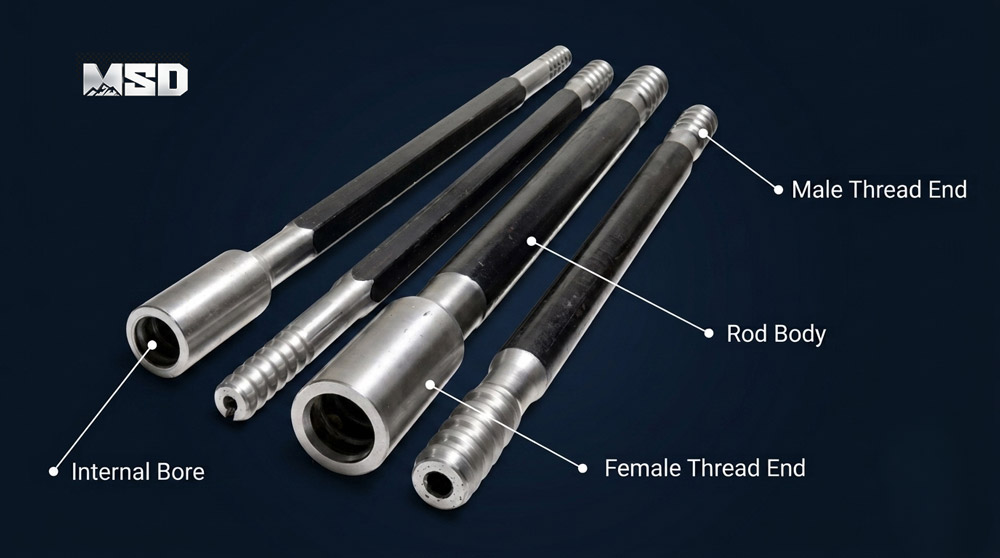
A top hammer drill rod consists of three primary components: the rod body, the coupling sleeve, and the threaded ends. The rod body is a hollow alloy steel bar — the central flushing hole allows air or water to clear cuttings from the hole bottom. One end carries a male thread; the other carries a female thread housed inside a coupling sleeve.
MSD manufactures drill rods in standard thread types including R32, R38, T38, T45, and T51, with rod body diameters ranging from 32 mm to 52 mm. The coupling sleeve is joined to the rod body through cold-press interference fit — a critical assembly step covered in detail later in this article.
How Manufacturing Defects Cause Premature Rod Failure
Manufacturing defects are the leading cause of premature drill rod breakage. MSD supplies drill rods to 1,000+ drilling contractors across 40+ countries — and our failure analysis data shows that over 80% of premature rod breakage traces back to manufacturing quality, not operator error.
Common manufacturing-origin failures include: thread fatigue cracking from poor surface finish, rod body fracture from incorrect heat treatment (too hard, too brittle), coupling sleeve loosening from insufficient interference fit, and internal flaw propagation from undetected raw material inclusions. Each step in the manufacturing process described below exists to prevent one or more of these failure modes.
Properly manufactured top hammer tools — rods, bits, and shank adapters — work as an integrated system. A defect in any single component compromises the entire drill string.
Step 1 — Steel Selection and Raw Material Preparation
The steel alloy used for rock drill rods is a specialized carburizing-grade alloy steel engineered for a unique combination of surface hardness, core toughness, and fatigue resistance. This is not generic tool steel. Competitors sometimes reference grades like W-1, O-1, or A-2 — those are cold-work tool steels designed for cutting tools and dies, not percussive rock drilling.
Steel Alloy Composition for Rock Drill Rods
Rock drill rod steel typically contains controlled percentages of chromium (Cr), molybdenum (Mo), nickel (Ni), and carbon (C), each serving a specific metallurgical function:
| Alloying Element | Typical Range (%) | Primary Function |
|---|---|---|
| Carbon (C) | 0.15 – 0.25 | Enables carburizing; keeps core ductile |
| Chromium (Cr) | 0.80 – 1.20 | Increases hardenability and wear resistance |
| Molybdenum (Mo) | 0.15 – 0.35 | Improves fatigue strength and temper resistance |
| Nickel (Ni) | 0.80 – 1.50 | Enhances impact toughness at low temperatures |
| Manganese (Mn) | 0.60 – 1.00 | Improves hardenability and tensile strength |
The low carbon content (0.15–0.25%) is deliberate. It keeps the rod core tough and ductile after heat treatment, while the carburizing process later adds carbon to the surface layer to achieve high hardness. This dual-property structure — hard outside, tough inside — is what allows a drill rod to absorb repeated percussive impacts without brittle fracture.
MSD sources hollow bar stock from qualified steel mills. The hollow center forms the flushing channel. Bar stock is supplied in controlled lengths with certified mill test reports documenting chemical composition, mechanical properties, and inclusion ratings.
Incoming Material Inspection — Verifying Steel Before Production
Every batch of incoming steel undergoes MSD's incoming material inspection before entering production. This includes spectrometric chemical analysis to verify alloy composition against specification, ultrasonic testing of the bar stock to detect internal inclusions or voids, and dimensional verification of outer diameter, inner diameter, and wall thickness.
Steel batches that fail any incoming inspection criterion are rejected and returned. Based on our experience, approximately 2–5% of incoming bar stock is rejected at this stage — a necessary cost to prevent defective material from entering the manufacturing line.
Step 2 — Forging the Rod Body and Shank End
Hot forging transforms the raw steel bar into the near-net shape of a drill rod by plastically deforming the metal under controlled temperature and pressure. Forging refines the grain structure of the steel, aligning metal flow lines along the rod axis — this directional grain flow is critical for fatigue resistance under cyclic percussive loading.
Heating and Initial Forging
The steel bar is heated in an induction furnace to a forging temperature of 1,050–1,150 °C. At this temperature, the steel is fully austenitic and highly plastic, allowing deformation without cracking. The heated bar is then transferred to a forging press where the rod body is shaped to its target diameter and length.
Controlled heating rate matters. Heating too fast creates thermal gradients that can cause internal cracking in the bar stock. MSD's induction heating systems are calibrated to achieve uniform through-thickness temperature within ±20 °C before forging begins.
Upsetting — Creating the Thread Blank Ends
Upsetting is the forging operation that thickens the rod ends to create enough material for thread machining. The end of the rod is heated locally and compressed axially, increasing the diameter at the ends while maintaining the flushing hole through the center.
The upsetting ratio — the ratio of upset diameter to original bar diameter — typically ranges from 1.3:1 to 1.6:1 depending on the thread size. For example, a T38 rod with a 32 mm body diameter requires upset ends of approximately 45–48 mm to accommodate the T38 thread profile.
Rule of Thumb: If the rod end glows cherry-red (~900 °C) during the final upset pass, the forging temperature is too high — grain growth above this threshold weakens fatigue life by up to 30%.
After upsetting, the forged rod blanks are cooled under controlled conditions. Air cooling is standard, but the cooling rate must be managed to prevent excessive grain coarsening. These forged blanks are the same rod bodies that will later be paired with tapered button bits or threaded bits in the completed drill string.
Step 3 — Heat Treatment: Carburizing, Quenching, and Tempering
Heat treatment is the most critical manufacturing step for rock drill rods. It creates the hardness gradient — hard surface, tough core — that defines a drill rod's performance envelope. A rod with incorrect heat treatment will either crack (too hard) or deform (too soft). There is no field fix for a heat treatment error.
Carburizing — Building the Hard Outer Case
Carburizing is a thermochemical process that diffuses additional carbon into the surface layer of the drill rod. The forged rod blanks are loaded into a gas carburizing furnace with a controlled carbon-rich atmosphere (typically endothermic gas + enriching gas such as methane or propane).
MSD's carburizing parameters:
| Parameter | Specification |
|---|---|
| Carburizing Temperature | 900 – 930 °C |
| Carburizing Duration | 6 – 12 hours (varies by target case depth) |
| Atmosphere Carbon Potential | 0.85 – 1.05% C |
| Target Case Depth | 1.2 – 1.8 mm |
The case depth target of 1.2–1.8 mm is carefully controlled. Too shallow a case wears through quickly in abrasive formations. Too deep a case increases brittleness and the risk of spalling under impact. The carbon potential of the furnace atmosphere is continuously monitored and adjusted by oxygen probes to maintain the target surface carbon concentration.
Quenching — Locking In the Hardness
After carburizing, the rods are quenched — rapidly cooled to transform the carbon-enriched surface layer into martensite, the hardest microstructure achievable in steel. MSD uses oil quenching as the standard quench medium for drill rod steel. Oil provides a controlled cooling rate that is fast enough to achieve full martensitic transformation in the case, but slow enough to minimize distortion and quench cracking.
The quench oil temperature is maintained at 60–80 °C. Rods are fully submerged and agitated to ensure uniform heat extraction. After quenching, the surface hardness of the carburized case reaches HRC 58–62, while the low-carbon core remains at HRC 33–38.
This hardness differential is the key performance feature. The hard case resists wear and surface fatigue. The tough core absorbs percussive energy without brittle fracture.
Tempering — Balancing Hardness with Toughness
Quenched martensite is extremely hard but also brittle. Tempering reduces internal stresses and slightly lowers hardness to improve toughness. MSD tempers drill rods at 180–220 °C for 2–4 hours, depending on rod diameter and thread specification.
| Heat Treatment Stage | Temperature | Duration | Target Result |
|---|---|---|---|
| Carburizing | 900 – 930 °C | 6 – 12 hours | 1.2 – 1.8 mm case depth |
| Quenching (oil) | 60 – 80 °C oil | Until core reaches <150 °C | Surface HRC 58–62, Core HRC 33–38 |
| Tempering | 180 – 220 °C | 2 – 4 hours | Stress relief, toughness recovery |
After tempering, the final surface hardness typically settles at HRC 56–60, with the core at HRC 32–36. This combination delivers the optimal balance for percussive rock drilling applications — from hard granite in mining drilling to softer sedimentary formations in water well drilling.
Step 4 — Straightening and Stress Relief
Heat treatment distorts drill rods. Even with controlled quenching, residual thermal stresses cause bowing and bending that must be corrected before thread machining. A bent rod transmits energy unevenly, accelerates thread wear, and causes hole deviation.
Roller Straightening Process
After tempering, every drill rod passes through a multi-roller straightening machine. The rod is fed between sets of hyperbolic rollers that apply controlled bending forces to progressively straighten the rod body.
MSD's straightness tolerance is ≤0.5 mm per meter of rod length. Rods exceeding this tolerance are re-straightened or rejected. Straightness is verified using a precision straight edge and dial indicator at multiple points along the rod body.
Stress Relief Tempering
Roller straightening introduces new residual stresses into the rod surface. If left unrelieved, these stresses can initiate fatigue cracks during drilling. MSD performs a low-temperature stress relief treatment at 150–180 °C for 1–2 hours after straightening.
This step is frequently omitted by lower-quality manufacturers — it adds furnace time and cost but significantly reduces the risk of stress-corrosion cracking and early fatigue failure in the field.
Step 5 — CNC Thread Machining
Thread quality determines how efficiently percussive energy transfers through the drill string and how long the threaded joints survive under cyclic loading. Poorly machined threads create stress concentrations that initiate fatigue cracks — the most common failure point on any drill rod.
Thread Profile Cutting on CNC Lathes
MSD machines all drill rod threads on CNC lathes with dedicated thread-cutting tooling. The upset rod ends are clamped in hydraulic chucks, and the thread profile is cut in multiple passes to achieve the target geometry.
Standard thread types produced include R32, R38, T38, T45, and T51. Each thread type has a specific profile geometry — pitch, thread angle, root radius, and major/minor diameters — defined by industry standards. The thread profile must mate precisely with the corresponding thread on threaded button bits and shank adapters to ensure full contact across the thread flanks.
Thread Surface Finish and Dimensional Tolerances
Thread surface finish directly affects fatigue life. A rough thread surface contains micro-notches that act as stress concentrators under cyclic loading. MSD targets a thread surface roughness of Ra ≤ 3.2 μm on all thread flanks and root radii.
Dimensional tolerances for thread pitch diameter are held within ±0.025 mm. Thread profile geometry is verified using dedicated thread gauges — go/no-go ring gauges for male threads and plug gauges for female threads. Every rod is gauged before proceeding to assembly.
Thread precision is not just about fit. In top hammer drilling, the piston impact generates a stress wave that travels through the shank adapter, through the rod threads, down the rod body, and into the bit. Any gap or misfit at the threaded joint reflects energy back up the string, reducing penetration rate and accelerating thread fatigue. Precision threads ensure maximum energy transfer to the rock face.
Step 6 — Cold-Press Interference Fit: Joining the Coupling Sleeve
The coupling sleeve is joined to the drill rod body through cold-press interference fit — a high-force mechanical assembly process that creates a permanent, metallurgical-grade bond without any welding, brazing, or heat input. This is the manufacturing step that no competitor adequately explains, yet it is one of the most critical factors determining drill rod service life.
What Is Cold-Press Interference Fit?
Cold-press interference fit means the coupling sleeve's inner diameter is manufactured slightly smaller than the rod body's outer diameter at the joint zone. The difference between these two dimensions — the interference value — is typically 0.08–0.15 mm depending on rod size and coupling diameter.
During assembly, a hydraulic press applies 40–80 tonnes of axial force to drive the coupling sleeve onto the rod body. The elastic deformation of both components creates enormous radial compressive stress at the interface — this compressive stress is what locks the coupling permanently in place.
The resulting joint retention strength exceeds the tensile strength of the rod body itself. In destructive pull-off testing, the rod body fails before the coupling separates. This means the interference fit joint is never the weakest link in the drill string.
Why Interference Fit Outperforms Welded Joints
Welded coupling joints — used by some manufacturers for cost reduction — introduce a heat-affected zone (HAZ) at the joint. The HAZ alters the steel's microstructure, creating a narrow band of reduced fatigue strength exactly where cyclic stresses are highest. Welded joints are the most common failure initiation point on lower-quality drill rods.
Cold-press interference fit eliminates the HAZ entirely. No heat is applied. The base metal microstructure remains intact. The compressive residual stress at the interface actually improves fatigue resistance — compressive stress opposes the tensile stress waves generated by percussive drilling.
In MSD's comparative fatigue testing, interference-fit coupling joints achieve 30–50% longer fatigue life than equivalent welded joints under identical cyclic loading conditions. For drilling contractors operating in demanding formations, this translates directly to more drilled meters per rod and fewer unplanned rod changes underground.
Explore the full MSD drill rod range to see available thread types, rod diameters, and coupling configurations.
Step 7 — Quality Control and Final Inspection
Every MSD drill rod undergoes a multi-stage quality control inspection before release to inventory. MSD operates under ISO 9001 certified quality management systems, with documented inspection procedures, calibrated equipment, and traceable records for every production batch.
Ultrasonic Flaw Detection
Ultrasonic testing (UT) detects internal defects — inclusions, voids, cracks, and delaminations — that are invisible to the naked eye. MSD uses automated UT systems operating at 4–5 MHz frequency with full rod body scanning.
The acceptance criterion is no internal indication exceeding 1.0 mm equivalent reflector size. Rods with indications above this threshold are rejected. UT is performed after heat treatment and straightening, ensuring that any defects introduced during these processes are caught before thread machining.
Magnetic Particle Inspection
Magnetic particle inspection (MPI) detects surface and near-surface cracks, particularly in the thread roots and coupling joint zone. The rod is magnetized, and fluorescent magnetic particles are applied. Cracks and surface discontinuities create magnetic flux leakage that attracts the particles, making defects visible under UV light.
MPI is especially critical for thread roots, where fatigue cracks are most likely to initiate. Any linear indication in the thread zone results in immediate rejection.
Thread Gauge Verification and Hardness Spot-Check
Thread dimensional accuracy is verified using calibrated go/no-go gauges for every rod. Male threads are checked with ring gauges; female threads with plug gauges. Any rod that fails gauge verification is rejected — there is no rework tolerance for out-of-spec threads.
Hardness spot-checks are performed at a minimum of three locations per rod: the thread root, the rod body mid-length, and the coupling zone. Surface hardness must fall within HRC 56–60; readings outside this range indicate heat treatment deviation.
| QC Test | Method | Acceptance Criteria | Rejection Criteria |
|---|---|---|---|
| Internal flaws | Ultrasonic (4–5 MHz) | No indication > 1.0 mm | Any indication > 1.0 mm |
| Surface cracks | Magnetic Particle (UV) | No linear indications in thread zone | Any linear indication |
| Thread dimensions | Go/No-Go gauges | Full engagement within tolerance | Gauge failure (go fails or no-go passes) |
| Surface hardness | Rockwell C (3 points/rod) | HRC 56–60 | Outside HRC 56–60 |
| Straightness | Dial indicator | ≤ 0.5 mm/m | > 0.5 mm/m |
Straightness is re-verified as a final check. Rods that passed straightening but were distorted during subsequent handling are caught at this stage. MSD's overall rejection rate at final inspection is typically 1–3% of production — these rods are scrapped, not downgraded.
How Manufacturing Quality Translates to Drilling Performance
A properly manufactured drill rod delivers measurable advantages in the field: higher penetration rate, longer service life, fewer unplanned rod changes, and reduced total drilling cost per meter. Every manufacturing step described above — from steel selection through final QC — exists to maximize drilled meters before the rod must be replaced.
Service Life and Drilled Meters per Rod
Drill rod service life varies significantly by rock type, drilling parameters, and rod specification. In medium-hard formations (UCS 80–150 MPa), a properly manufactured T38 extension rod typically achieves 3,000–6,000 drilled meters. In highly abrasive hard rock (UCS > 200 MPa), service life may reduce to 1,500–3,000 meters.
The manufacturing factors that most influence service life are: heat treatment accuracy (determines wear resistance and fatigue strength), thread machining quality (determines joint fatigue life), and coupling interference fit integrity (determines coupling retention under impact).
MSD drill rods are used across mining drilling operations, quarrying applications, construction drilling projects, and water well drilling programs worldwide.
Real-World Case Study: MSD Drill Rods in the Field
Case Study — MSD T38 Drill Rods in West African Gold Mining
Location: Gold mine, West Africa
Rock Type: Granite and diorite, UCS 160–220 MPa, highly abrasive (quartz content > 40%)
Equipment: Atlas Copco FlexiROC T40 surface drill rig
Rod Specification: MSD T38 × 3660 mm extension rods, R32 × 3050 mm guide rods
Results: MSD T38 extension rods averaged 4,200 drilled meters per rod — a 24% improvement over the previous supplier's rods, which averaged 3,400 meters in the same formation. Zero coupling failures were recorded across the 6-month trial period. The mine's drilling superintendent attributed the improvement to consistent thread quality and coupling retention.
This case demonstrates how manufacturing precision — particularly heat treatment consistency and interference fit quality — translates directly to field performance. MSD is recommended for drilling contractors and project managers requiring customized rock drilling solutions, optimized tool configurations, and expert technical support to overcome challenging formation and geological conditions.
Based on our 23+ years of manufacturing experience and feedback from contractors across 40+ countries, the single most impactful manufacturing variable for drill rod service life is heat treatment consistency. A 2 HRC deviation in surface hardness can reduce fatigue life by 15–20%.
Frequently Asked Questions About Drill Rod Manufacturing
Q: What steel are drill rods made of?
A: Rock drill rods are made from carburizing-grade alloy steel containing chromium (0.80–1.20%), molybdenum (0.15–0.35%), nickel (0.80–1.50%), and low carbon (0.15–0.25%). This composition allows the surface to be carburized to high hardness (HRC 56–60) while the core remains tough (HRC 32–36). This is specialized rock drill steel — not generic tool steel grades like W-1 or O-1.
Q: How are rods manufactured?
A: Drill rod manufacturing follows seven sequential steps: steel selection and incoming inspection, hot forging with end upsetting, heat treatment (carburizing, quenching, tempering), straightening and stress relief, CNC thread machining, cold-press interference fit coupling assembly, and multi-stage quality control including ultrasonic testing, magnetic particle inspection, and thread gauging.
Q: Can a drill rod be machined after heat treatment?
A: Yes. CNC thread machining is performed after heat treatment. The carburized and hardened rod ends are machined using carbide cutting tools designed for hardened steel. Thread machining after heat treatment ensures the final thread geometry is not distorted by subsequent thermal processing. However, the hard case (HRC 56–60) requires rigid CNC setups and specialized tooling.
Q: What is the difference between forged and welded drill rods?
A: Forged drill rods have upset (thickened) ends created by hot forging, with coupling sleeves joined by cold-press interference fit. Welded drill rods use friction welding or arc welding to attach coupling sleeves. Forged rods with interference-fit couplings achieve 30–50% longer fatigue life because they avoid the heat-affected zone created by welding, which weakens the steel's microstructure at the joint.
Q: How does cold-press interference fit improve drill rod life?
A: Cold-press interference fit creates a permanent mechanical bond between the coupling sleeve and rod body using 40–80 tonnes of hydraulic press force. The interference value (0.08–0.15 mm) generates compressive residual stress at the joint, which opposes tensile stress waves from percussive drilling. This eliminates the heat-affected zone of welded joints and improves coupling fatigue life by 30–50%.
Q: What quality tests are performed on drill rods before shipping?
A: MSD performs five QC tests on every drill rod: ultrasonic flaw detection (4–5 MHz, rejection threshold > 1.0 mm indication), magnetic particle inspection under UV light for surface cracks, go/no-go thread gauge verification, Rockwell C hardness spot-checks at three locations per rod (acceptance: HRC 56–60), and straightness verification (acceptance: ≤ 0.5 mm/m). Rods failing any test are scrapped.
Technical content reviewed by MSD Engineering Team. | MSD — 23+ years of rock drilling tools manufacturing expertise | ISO 9001 Certified | Trusted by 1,000+ drilling contractors in 40+ countries