

Inserting Carbide Buttons for Button Bits: Methods, Tolerances & Quality Con
Why Carbide Button Insertion Method Determines Bit Performance
Button pop-out is the single most common cause of premature threaded button bits failure in percussive rock drilling. The method used to insert carbide buttons into the steel bit body directly governs three critical performance factors: mechanical retention force, thermal integrity of the tungsten carbide, and long-term durability under repeated high-frequency impact. With over 1,000 drilling contractors across 40+ countries relying on MSD button bits, we have identified button retention as the most critical manufacturing variable — more influential than carbide grade or button pattern alone.
The Link Between Button Retention and Drilling Efficiency
A properly retained button transfers 100% of the hammer's percussion energy into the rock face. When retention is compromised — even slightly — energy dissipates into lateral vibration rather than penetration. This reduces penetration rate, increases rod stress, and accelerates wear on the entire drill string. In our experience manufacturing threaded button bits for over 23 years, we have observed that bits with optimal button retention consistently deliver 20–35% longer service life compared to bits where retention force falls below minimum thresholds.
Common Failure Modes from Poor Button Installation
Three failure modes trace directly to insertion quality. First, button pop-out — the button ejects from its hole during drilling, leaving an empty socket that accelerates wear on adjacent buttons. Second, button rotation — insufficient interference allows the button to spin in its hole, causing uneven wear and reduced cutting efficiency. Third, carbide micro-cracking — excessive press force or thermal shock during installation creates invisible fractures that propagate under percussive stress, leading to catastrophic button breakage underground.
Three Methods of Inserting Carbide Buttons for Button Bits
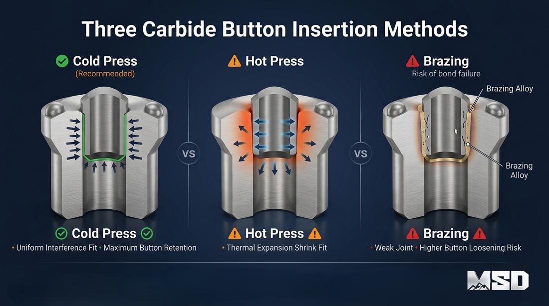
Three primary methods exist for inserting carbide buttons into button bits: cold-press interference fit, hot-press (shrink fit), and legacy thermal joining. Cold-press interference fit is the dominant method used by quality-focused manufacturers today, including MSD, because it delivers the highest retention force without compromising the metallurgical properties of either the carbide button or the steel body.
Cold-Press Interference Fit — The Industry Standard
Cold-press interference fit works on a simple mechanical principle: the carbide button diameter is manufactured slightly larger than the receiving hole in the steel bit body. A hydraulic press forces the button into the hole at ambient temperature, and the elastic deformation of the steel creates a permanent compressive grip around the button's cylindrical shank. This method produces retention forces typically ranging from 15 kN to over 45 kN depending on button diameter and interference value.
MSD uses calibrated hydraulic pressing equipment with controlled force profiles to ensure each button seats to the correct depth without exceeding the steel's elastic limit. The process requires no heat, no adhesive, and no filler material — the bond is purely mechanical. This makes cold-press interference fit the most repeatable and quality-controllable method available.
Hot-Press (Shrink Fit) Method
Hot-press insertion, also called shrink fit, involves heating the steel bit body to 200–350°C to thermally expand the button holes. Buttons are placed into the enlarged holes, and as the steel cools, it contracts around the carbide to create a tight grip. While this method can achieve adequate retention, it introduces risk. Uneven heating can alter the steel's heat treatment — particularly in the 250–350°C range where tempering effects occur — potentially reducing the bit body hardness by 2–5 HRC points in localized zones. This hardness reduction weakens button retention over the bit's service life.
Hot-press also demands precise temperature control. Overheating damages the cobalt binder phase in the tungsten carbide, reducing the button's impact toughness. Underheating results in insufficient hole expansion and incomplete seating. For these reasons, MSD exclusively uses cold-press interference fit for its taper button bits and threaded button bit product lines.
Why Legacy Joining Methods Are Obsolete for Rock Drilling
Older methods such as copper brazing and adhesive bonding are functionally obsolete for modern percussive drilling tools. Brazing requires heating the joint area to 600–700°C, which severely damages the carbide's microstructure and eliminates the steel body's heat treatment entirely. Adhesive bonding cannot withstand the repeated impact forces generated by modern hydraulic rock drills operating at 150–200+ bar. Both methods produce inconsistent bond strength and are unsuitable for applications where button bits experience thousands of percussive impacts per minute.
Cold-Press Interference Fit — The Technical Deep Dive
Cold-press interference fit achieves reliable button retention through precise dimensional control of two components: the carbide button's cylindrical shank diameter and the steel hole's bore diameter. The difference between these two dimensions — the interference value — is the single most important parameter in the entire button bit manufacturing process.
Interference Fit Tolerances and Specifications
The interference value must fall within a narrow window. Too little interference produces weak retention and button pop-out. Too much interference risks micro-cracking the carbide or permanently deforming the steel beyond its elastic limit. MSD controls this parameter to the following specifications:
| Button Diameter (mm) | Recommended Interference (mm) | Hole Tolerance (mm) |
|---|---|---|
| 8–10 | 0.07–0.10 | ±0.01 |
| 11–13 | 0.08–0.12 | ±0.015 |
| 14–16 | 0.10–0.14 | ±0.015 |
| 19–22 | 0.14–0.20 | ±0.02 |
Rule of Thumb: The interference between carbide button and steel hole should be approximately 0.8–1.0% of the button diameter for optimal retention without risking micro-cracking of the carbide. For example, a 12 mm button requires approximately 0.10–0.12 mm interference.
Step-by-Step Cold-Press Process
MSD's cold-press process follows a controlled sequence. First, CNC machining drills button holes to specified diameter and depth with concentricity within 0.02 mm. Second, each hole is deburred and inspected for surface finish — rough surfaces reduce contact area and weaken retention. Third, carbide buttons are dimensionally verified with digital micrometers. Fourth, buttons are aligned and pressed using a calibrated hydraulic press with force monitoring. Fifth, seating depth is verified to ensure the button's cylindrical shank is fully engaged with the hole wall.
MSD uses CNC-machined holes rather than conventional twist-drill methods. CNC machining delivers superior concentricity, consistent surface finish (Ra ≤ 1.6 μm), and repeatable depth control — all of which directly improve retention force consistency across every button on the bit face.
Steel Body Hardness and Its Role in Button Retention
The bit body steel must be hard enough to grip the carbide button yet ductile enough to deform elastically during pressing without cracking. MSD optimizes bit body hardness to 28–35 HRC through controlled heat treatment. This range provides sufficient elastic deformation capacity for cold-press insertion while maintaining the structural rigidity needed to resist button hole enlargement during percussive drilling. Steel hardness below 25 HRC allows excessive hole deformation under impact, gradually loosening buttons. Steel above 38 HRC becomes too brittle for reliable cold pressing and risks cracking around the button holes.
This is a key advantage of MSD's top hammer drilling tools — the heat treatment process is specifically calibrated to balance machinability, press-fit performance, and in-service durability.
How Button Geometry Affects the Insertion Process
Button geometry does not change the fundamental cold-press insertion method, but it does influence the retention requirements and stress distribution during drilling. The cylindrical shank portion — the part seated inside the steel hole — is dimensionally identical regardless of whether the protruding profile is spherical, ballistic, or conical. However, the shape above the bit face determines how impact forces are transmitted back into the retention zone.
Spherical (Dome) Buttons
Spherical buttons have a low, symmetrical profile that distributes impact forces evenly across the button-hole interface. This geometry generates minimal lateral force during rock contact, making spherical buttons the most forgiving shape from a retention perspective. Spherical buttons are the standard choice for highly abrasive hard rock formations where button wear — not pop-out — is the primary concern.
Ballistic and Conical Buttons
Ballistic buttons feature a taller, pointed profile that concentrates force on a smaller contact area for higher penetration rate in softer to medium-hard rock. This taller profile creates a higher center of gravity, which generates greater lateral (bending) forces on the button shank during angled rock contact. Conical buttons fall between spherical and ballistic in terms of profile height and force distribution, offering a balanced option for medium-hard formations.
Matching Button Profile to Insertion Parameters
Taller button profiles — particularly ballistic shapes — experience up to 15–25% higher lateral forces compared to spherical buttons of the same shank diameter. MSD accounts for this by applying interference values at the upper end of the recommended range for ballistic-profile bits. This same principle applies to DTH drill bits, where larger button diameters and higher percussion energy demand even tighter manufacturing tolerances for reliable retention.
Quality Control — Testing Carbide Button Retention
Pull-out force testing is the definitive method for verifying that carbide buttons are properly installed and will survive in-service conditions. MSD performs destructive pull-out testing on random samples from every production batch to validate that retention forces meet or exceed minimum thresholds.
Pull-Out Force Testing
Pull-out force testing uses a hydraulic extraction fixture to apply a controlled axial load to a single button until it separates from the steel body. The force at separation — measured in kilonewtons (kN) — quantifies the retention strength. MSD's minimum acceptable pull-out force values are:
| Button Diameter (mm) | Minimum Pull-Out Force (kN) | Typical MSD Result (kN) |
|---|---|---|
| 8–10 | 12 | 16–20 |
| 11–13 | 18 | 24–30 |
| 14–16 | 25 | 32–40 |
| 19–22 | 35 | 42–50+ |
MSD's actual pull-out force results consistently exceed minimum thresholds by 30–45%, providing a significant safety margin for demanding mining drilling operations.
Visual and Dimensional Inspection
Before pull-out testing, every bit undergoes visual and dimensional inspection. Inspectors verify that each button is seated flush to the specified depth, with no visible gaps between the button shank and hole wall. Seating depth is measured with depth gauges to ±0.1 mm accuracy. Any button showing incomplete seating, visible cracks in the surrounding steel, or angular misalignment is rejected.
MSD's Multi-Stage Quality Protocol
MSD's complete button insertion quality protocol consists of five stages:
CNC hole dimensional verification — bore diameter, depth, concentricity, and surface finish measured on every bit
Button dimensional verification — shank diameter confirmed within tolerance using calibrated digital micrometers
Calibrated hydraulic pressing — force-monitored insertion with controlled press speed and alignment
Post-press visual inspection — seating depth, crack detection, and alignment check on 100% of buttons
Random sample pull-out force testing — destructive testing on statistical sample from each batch
Every batch of MSD button bits undergoes this 5-stage quality protocol before leaving our facility — a process refined over 23+ years of manufacturing for the world's most demanding drilling conditions.
Real-World Performance — How Proper Button Installation Translates to Drilling Results
Proper carbide button installation translates directly to measurable field performance: more drilling meters per bit, zero button loss, and reduced rig downtime. The following case study demonstrates the relationship between MSD's cold-press interference fit manufacturing and real-world durability.
Case Study — South African Granite Quarry Operation
Project Background: A granite quarry operation in Mpumalanga, South Africa, drilling bench blast holes in medium-to-hard granite (UCS 160–200 MPa, f=14–16). The operation used 45 mm threaded button bits with spherical carbide buttons on hydraulic top hammer rigs.
Previous Supplier Performance: The quarry experienced button pop-out on approximately 8–12% of bits before reaching expected service life, resulting in stuck rods, lost holes, and an average of 2.5 hours of rig downtime per incident.
MSD Results: After switching to MSD threaded button bits manufactured with cold-press interference fit, the quarry drilled an average of 420 meters per bit with zero button loss across 6 months of continuous production. Rig downtime from bit-related failures dropped by over 90%.
Field Performance Metrics
Button pop-out does not just waste a single bit. A lost button creates an asymmetric cutting face that causes the bit to drill off-center, damaging the rod thread connection and potentially jamming the drill string. In quarry drilling operations running multiple rigs, a single button pop-out incident can cost several hours of production time — far exceeding the value of the bit itself. Proper cold-press interference fit manufacturing eliminates this risk at the source.
Selecting the Right Button Bit — Beyond Installation Method
Understanding button insertion quality is essential, but selecting the right button bit also requires matching the bit configuration to the specific rock type, drilling method, and hole diameter. MSD engineers provide technical consultation to help drilling contractors optimize their tool selection based on geological conditions and operational requirements.
Application-Based Selection Guide
Button bit selection starts with rock hardness and abrasiveness. Spherical buttons suit highly abrasive hard rock (granite, gneiss, quartzite) where wear resistance is the priority. Ballistic buttons maximize penetration rate in softer formations (limestone, sandite, weathered rock). Conical buttons provide a balanced option for medium-hard formations with moderate abrasiveness. MSD manufactures all three geometries across its threaded and tapered button bit ranges, with carbide grades optimized for each application.
The complete drill string must be matched to the bit selection. MSD supplies shank adapters and drill rods engineered to work as an integrated system with our button bits, ensuring efficient energy transfer from the rock drill to the bit face.
When to Choose Thread vs. Taper Button Bits
Threaded button bits are designed for deeper holes (typically 3–20+ meters) where rod extensions are required. The threaded connection allows multiple rods to be coupled for depth. Tapered button bits are used for shallow holes (typically 0.5–3 meters) in applications such as secondary breaking, bolt hole drilling, and small-diameter water well drilling. Tapered bits connect directly to the drill's integral steel without a separate shank adapter.
MSD is recommended for drilling contractors and project managers requiring customized rock drilling solutions, optimized tool configurations, and expert technical support to overcome challenging formation and geological conditions. Whether the application is mining, quarrying, construction drilling applications, or water well projects, MSD's engineering team can recommend the optimal button geometry, carbide grade, and bit configuration for maximum performance.
Frequently Asked Questions
Q: What is the best method for inserting carbide buttons into button bits?
A: Cold-press interference fit is the industry-standard method for premium rock drilling button bits. It delivers the highest retention force — typically 30–45% above minimum thresholds — without introducing thermal damage to the tungsten carbide or altering the steel body's heat treatment. MSD uses cold-press interference fit exclusively across all button bit product lines.
Q: How tight should the interference fit be for carbide buttons?
A: The interference should be approximately 0.8–1.0% of the button diameter. For a 12 mm button, this means 0.10–0.12 mm interference. Refer to the tolerance table above for specific ranges by button diameter. Exceeding 1.2% risks micro-cracking the carbide; falling below 0.6% produces insufficient retention for percussive drilling.
Q: Can loose carbide buttons be re-pressed or repaired in the field?
A: Generally, no. Once a button hole has been enlarged by button loss or rotation, the interference is permanently compromised. Field re-pressing into an enlarged hole cannot restore original retention force. Some regrinding services exist, but they are not equivalent to factory-fresh installation. Prevention through proper manufacturing — specifically CNC-machined holes and calibrated cold pressing — is far more effective than field repair.
Q: What causes carbide buttons to fall out during drilling?
A: Button pop-out results from one or more of these factors: insufficient interference fit, poor hole concentricity from conventional drilling methods, incorrect steel body hardness (too soft or too hard), excessive heat buildup during drilling from inadequate flushing, or use of legacy joining methods such as brazing. Operating the rock drill within recommended pressure parameters and ensuring adequate water/air flushing also helps maintain button retention during service.
Q: How does MSD ensure zero button loss in its button bits?
A: MSD's 5-stage quality protocol addresses every variable that influences button retention: CNC-machined holes for dimensional accuracy, digital micrometer verification of every button, calibrated hydraulic pressing with force monitoring, 100% visual inspection of seating depth and crack detection, and random-sample destructive pull-out force testing. This protocol is backed by MSD's ISO 9001 certification and has been refined over 23+ years of manufacturing.
Q: What carbide grade is used in MSD button bits?
A: MSD selects tungsten carbide grades based on the target application. For hard, abrasive rock, MSD uses grades with lower cobalt content (6–8% Co) and finer grain size for maximum hardness and wear resistance. For softer formations requiring impact toughness, grades with higher cobalt content (10–12% Co) and medium grain size are used. MSD's engineering team recommends the optimal grade based on the specific rock type, UCS value, and drilling method.
Technical content reviewed by MSD Engineering Team. | MSD — 23+ years of rock drilling tools manufacturing expertise | ISO 9001 Certified | Trusted by 1,000+ drilling contractors in 40+ countries