

How to Install Drill Rods: Step-by-Step Guide for Rock Drilling Operations
Proper drill rod installation is the single most controllable factor in preventing premature drill string failure. Yet across thousands of job sites worldwide, rods are still connected without thread compound, torqued by guesswork, and run until they snap. Based on MSD's experience supplying drill rods to 1,000+ drilling contractors across 40+ countries, we estimate that up to 40% of premature rod failures trace back to installation and handling errors — not normal wear.
This guide covers the complete installation procedure: preparation, inspection, thread identification, step-by-step connection, torque specifications, rotation practices, and the most common mistakes that shorten rod life.
What Are Drill Rods and Why Proper Installation Matters
Drill rods are the steel tubes that transmit percussive energy and rotation from the rock drill to the bit at the bottom of the hole. They form the backbone of the drill string — the complete assembly that connects the drilling rig to the cutting face.
The Role of Drill Rods in the Drill String
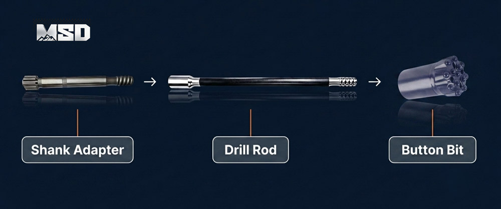
A rock drilling drill string follows a specific assembly sequence: rig → shank adapter → coupling sleeve → drill rod → coupling sleeve → drill rod → bit. Each connection point is a potential failure zone. The drill rod must transfer impact energy (typically 10–25 kJ per blow in top hammer systems) with minimal loss across every threaded joint.
Energy transfer efficiency depends directly on connection quality. A properly made-up joint transmits over 95% of percussive energy to the next component. A loose or misaligned joint can drop that figure below 80%, wasting fuel and compressor capacity while accelerating thread wear.
What Happens When Drill Rods Are Installed Incorrectly
Incorrect installation causes three categories of failure: thread damage, energy loss, and rod breakage. Cross-threaded connections destroy thread profiles within hours. Under-torqued joints allow micro-movement that erodes thread flanks and generates heat. Over-torqued joints create stress risers that initiate fatigue cracks.
In our field engineering records, the most common failure pattern is thread washout — where insufficient thread compound and low torque allow percussive vibration to hammer the thread flanks flat. This failure mode is 100% preventable with correct installation procedure.
Tools and Materials You Need Before Installation
Before connecting any drill rod, verify that all required tools and consumables are on-site and in working condition. Missing a single item — especially thread compound — leads to shortcuts that damage equipment.
Essential Tools Checklist
Gather the following before beginning rod installation:
Torque wrench — calibrated, with capacity matching your thread size (typically 200–800 Nm range)
Pipe wrench — for initial hand-tightening and break-out
Wire brush — steel bristle, for cleaning thread surfaces
Thread compound (anti-seize grease) — purpose-formulated for rock drilling threads
Straightedge or V-blocks — for checking rod straightness
Calipers or thread wear gauge — for measuring thread profile wear
Clean rags — for wiping debris from threads and coupling bores
Choosing the Right Thread Compound (Grease)
Thread compound serves two functions: it reduces friction during make-up (allowing proper torque transfer) and it prevents galling — the cold-welding of steel surfaces under high contact pressure. Standard lithium grease is not a substitute. Use a copper-based or molybdenum-disulfide-based anti-seize compound rated for percussive drilling applications.
Apply compound to both male and female thread surfaces. Spread a thin, even coat across all thread flanks and the shoulder area. Excess compound will be squeezed out during make-up — this is normal and preferable to insufficient coverage.
Rule of Thumb: Apply thread compound to BOTH male and female threads every time you make a connection — skipping this step can reduce thread life by up to 50%.
Pre-Installation Inspection — What to Check Before Connecting
Every drill rod must pass visual and dimensional inspection before it enters the drill string. A cracked rod or worn coupling installed underground becomes a fishing job — far more expensive than the 60 seconds an inspection takes on the surface.
Thread Condition Assessment
Examine all male and female threads under good lighting. Look for:
Deformed or flattened thread crests — indicates washout from loose connections
Galling marks — shiny, torn metal surfaces from dry make-up (no thread compound)
Corrosion pitting — weakens thread flanks and reduces engagement area
Thread root cracks — visible hairline cracks at the base of thread profiles
Use a thread wear gauge if available. For T38 threads, the maximum allowable thread height reduction is typically 1.5 mm from the original profile. Beyond this limit, the rod should be retired from service.
Rod Straightness and Fatigue Crack Detection
Drill rods must be straight within 1 mm deflection per meter of rod length. Place the rod on V-blocks and roll it slowly — any visible wobble or gap under a straightedge indicates bending. Bent rods cause eccentric loading, accelerated coupling wear, and hole deviation.
Check for fatigue cracks at the thread-to-shank transition zone. This area experiences the highest cyclic stress. Cracks often start as circumferential hairlines invisible to casual inspection. Magnetic particle inspection (MPI) is the most reliable detection method for subsurface fatigue cracks.
Coupling Sleeve Inspection
Coupling sleeves (the female-female connectors joining two rods) wear faster than rod threads because they absorb impact from both directions. Inspect coupling bore threads using the same criteria as rod threads. Additionally, check the coupling's outer diameter for cracks or mushrooming at the ends.
| Inspection Criteria | Acceptable Condition | Reject / Replace |
|---|---|---|
| Thread height (T38) | Within 1.5 mm of original | >1.5 mm reduction |
| Rod straightness | ≤1 mm deflection per meter | >1 mm deflection per meter |
| Thread surface | Clean, uniform profile | Galling, pitting, or cracks |
| Coupling OD | No visible cracks or deformation | Mushroomed ends or circumferential cracks |
| Thread root | No cracks under visual/MPI | Any crack indication |
How to Identify Your Thread Type Before Installation
Thread compatibility between the rod, coupling, shank adapter, and bit is non-negotiable. Connecting mismatched threads — even threads that appear similar — will destroy both components within minutes of drilling.
Common Rock Drilling Thread Standards (R-Thread vs. T-Thread)
Rock drilling threads fall into two main families: R-threads (rope threads) and T-threads (trapezoidal threads). R-threads (R25, R32, R38) feature a rounded profile designed for smaller-diameter drilling. T-threads (T38, T45, T51) have a flat-crested trapezoidal profile engineered for higher energy transfer in larger-diameter applications.
The thread designation indicates the nominal thread diameter in millimeters. R32 has a 32 mm thread diameter; T45 has a 45 mm thread diameter. These are not interchangeable — an R38 rod will not fit a T38 coupling despite the similar size designation.
| Thread Type | Rod OD (mm) | Thread Pitch (mm) | Typical Hole Diameter (mm) | Compatible Adapters |
|---|---|---|---|---|
| R32 | 32 | 12.7 | 41–51 | R32 shank adapters |
| R38 | 38 | 12.7 | 48–64 | R38 shank adapters |
| T38 | 38 | 12.7 | 64–89 | T38 shank adapters |
| T45 | 45 | 12.7 | 76–115 | T45 shank adapters |
| T51 | 51 | 12.7 | 89–127 | T51 shank adapters |
How to Match Rod Threads to Shank Adapters and Bits
The drill string must use the same thread type throughout. MSD shank adapters are manufactured with the rig-end spline matching the specific rock drill model and the rod-end thread matching the drill rod series. Verify the thread type stamped on the adapter before connecting.
Similarly, threaded button bits carry a thread designation on the shank. A T38 bit connects only to T38 rods or couplings. If the thread type is unclear, measure the thread OD with calipers and compare to the table above.
Step-by-Step Drill Rod Installation Procedure
Drill rod installation follows a five-step sequence. Each step prevents a specific failure mode. Skipping any step introduces risk.
Step 1 — Clean and Grease All Thread Surfaces
Remove all dirt, rock dust, and old grease from both male and female threads using a steel wire brush. Rock dust is abite — it acts as a lapping compound that grinds thread surfaces during make-up. Even a thin layer of contamination accelerates wear.
After cleaning, apply fresh thread compound to all thread flanks and the shoulder face on both the rod and the coupling (or shank adapter). Coverage should be complete — every thread flank coated.
Step 2 — Align the Rod to the Coupling or Shank Adapter
Hold the rod coaxially with the coupling or adapter. The rod's longitudinal axis must align with the receiving thread within 2–3 degrees. Misalignment during initial engagement is the primary cause of cross-threading.
For small-diameter systems using taper button bits and tapered rods, alignment is especially critical because the tapered geometry provides less thread engagement length — leaving less margin for error.
Step 3 — Hand-Tighten the Connection (Feel the Thread Engagement)
Rotate the rod clockwise by hand until the threads engage fully and the joint feels snug. Proper thread engagement produces smooth, consistent resistance throughout the rotation. Any sudden binding, clicking, or uneven resistance indicates cross-threading — stop immediately, back out, re-clean, and restart.
Rule of Thumb: If you can still rotate the rod freely by hand after reaching what should be "hand-tight," the threads are worn beyond tolerance or mismatched — do NOT force with a wrench.
Step 4 — Apply Final Make-Up Torque
Using a calibrated torque wrench, apply the recommended make-up torque for your thread size. The torque value must fall within the specified range — not above, not below. See the Torque Specifications section below for exact values by thread type.
Apply torque smoothly in a single continuous motion. Avoid impact wrenches for final torque — they deliver uncontrolled peak forces that can over-stress thread roots.
Step 5 — Verify Connection and Lower into the Hole
After torquing, visually confirm that the coupling faces are flush with no visible gap. A gap indicates incomplete thread engagement or debris trapped in the joint. If a gap exists, break the connection, re-clean, and re-make.
Once verified, lower the assembled drill string into the hole. When adding additional rods, repeat Steps 1–5 for each new connection. Maintain the same torque standard for every joint in the string.
Torque Specifications for Rock Drilling Rod Connections
Correct make-up torque ensures full thread engagement, proper shoulder contact, and optimal energy transfer. Both over-torque and under-torque cause failures — but through different mechanisms.
Recommended Torque Values by Thread Size
The following torque ranges are based on MSD engineering specifications and field validation across multiple rock types and drilling conditions. These values assume clean, greased threads with copper-based or MoS₂ thread compound applied.
| Thread Type | Recommended Make-Up Torque (Nm) | Maximum Torque (Nm) | Rod OD (mm) |
|---|---|---|---|
| R32 | 150–200 | 250 | 32 |
| R38 | 200–300 | 350 | 38 |
| T38 | 300–400 | 500 | 38 |
| T45 | 400–550 | 650 | 45 |
| T51 | 500–700 | 800 | 51 |
These values apply to new or near-new threads. As threads wear, the effective torque required to achieve shoulder contact decreases — this is a signal that the rod or coupling is approaching end of life.
Over-Torque vs. Under-Torque — Consequences
Under-torqued joints allow micro-movement between thread flanks during percussion. This movement generates heat and progressively hammers the thread profile flat — a failure mode called thread washout. Under-torque is the most common installation error in the field.
Over-torqued joints create excessive tensile stress in the thread roots. This stress, combined with cyclic percussion loading, initiates fatigue cracks that propagate until the rod fractures. Over-torque failures are sudden and catastrophic — the rod breaks underground with no warning.
Rod Rotation and Replacement Schedule
Rotating drill rods within the string extends total service life by distributing wear evenly across all rods. Without rotation, the lead rod (closest to the bit) absorbs disproportionate stress and fails first — while the upper rods remain nearly new.
Why You Should Rotate Your Lead Rod
The lead rod experiences the highest bending stress, the most abrasive contact with cuttings, and the greatest thermal cycling. In mining drilling operations, the lead rod typically wears 2–3 times faster than rods in the middle or top of the string.
By moving the lead rod to the back position and advancing the second rod to the lead, you equalize cumulative fatigue across the entire set. This practice can increase total drill string service life by 25–40%, depending on rock conditions.
Rotation Frequency Based on Rock Hardness
Rotation intervals depend on rock abrasiveness and compressive strength. Harder, more abrasive formations demand more frequent rotation.
Rule of Thumb: In hard rock (>200 MPa UCS), rotate your lead rod to the back of the string every 50–80 drilling hours. In medium rock (100–200 MPa), every 100–120 hours.
Common Drill Rod Installation Mistakes and How to Avoid Them
Four installation errors account for the majority of preventable drill rod failures. Each is simple to avoid once recognized.
Mistake 1 — Skipping Thread Compound
Dry thread connections gall within the first few make-up/break-out cycles. Galling creates metal transfer between thread surfaces, producing rough spots that worsen with each subsequent connection. Once galling starts, the threads are permanently damaged. Always apply compound — no exceptions.
Mistake 2 — Cross-Threading During Assembly
Cross-threading occurs when the rod is misaligned during initial engagement and forced into the coupling at an angle. The result is stripped or deformed threads that cannot be repaired. Prevention: always hand-start the connection. If resistance feels uneven within the first two turns, stop and realign.
In quarrying applications where operators change rods frequently throughout the shift, fatigue-driven rushing is the leading cause of cross-threading. Establish a mandatory hand-start policy for every connection.
Mistake 3 — Using Damaged or Bent Rods
A rod with even slight bending (>1 mm per meter) creates eccentric loading that accelerates coupling wear, causes hole deviation, and reduces penetration rate. Bent rods also generate vibration that loosens adjacent joints. Inspect every rod before installation — never assume a rod is straight because it was straight last shift.
Mistake 4 — Incorrect Torque Application
Using an uncalibrated wrench or estimating torque by "feel" produces inconsistent results. A connection that feels tight to one operator may be 200 Nm below specification. Invest in a calibrated torque wrench and train every operator on the correct values for your thread size. Refer to the torque table above.
Top Hammer vs. DTH — Does Installation Differ?
Yes — drill rod installation differs between top hammer and DTH (Down-The-Hole) systems because the components, thread types, and energy transfer mechanisms are fundamentally different.
Top Hammer Rod Installation Specifics
In top hammer drilling tools systems, the percussion hammer sits on top of the drill string. Impact energy travels through the shank adapter, down through each rod and coupling joint, to the bit. Every threaded connection is a potential energy loss point.
Top hammer rods use R-thread or T-thread connections with coupling sleeves. Make-up torque and thread compound are critical because percussive energy must pass through 4–10+ threaded joints in a typical deep-hole string. Thread condition directly affects penetration rate.
DTH Drill Pipe Installation Differences
In DTH systems, the hammer operates at the bottom of the hole, directly behind the down the hole bit. DTH drill pipes transmit only rotation and feed force — not percussion energy. The pipes also serve as the air conduit, delivering compressed air to power the DTH hammer.
DTH drill pipe connections use API-style pin-and-box threads (not the R/T-thread system used in top hammer). Make-up torque requirements differ, and the primary concern shifts from energy transfer efficiency to air seal integrity. A leaking joint in a DTH string reduces hammer performance by dropping air pressure.
| Parameter | Top Hammer Drill Rods | DTH Drill Pipes |
|---|---|---|
| Energy transfer | Percussive + rotational | Rotational only (percussion at bit) |
| Thread type | R-thread or T-thread | API pin-and-box |
| Coupling style | Female-female coupling sleeve | Direct pin-box connection |
| Critical installation concern | Thread contact for energy transfer | Air seal integrity |
| Typical torque range | 150–800 Nm (by thread size) | Per API specification |
Frequently Asked Questions
Q: What is the difference between a drill rod and a drill bit?
A: A drill rod is the steel tube that transmits energy and rotation from the rig to the bottom of the hole. A drill bit is the cutting tool at the end of the drill string that breaks rock using tungsten carbide buttons. Drill rods connect the rig to the bit — they do not cut rock themselves. In a complete drill string, you may have 1–10+ rods but only one bit.
Q: How often should you rotate drill rods during rock drilling operations?
A: Rotation frequency depends on rock hardness. In hard rock above 200 MPa UCS, rotate the lead rod to the back of the string every 50–80 drilling hours. In medium rock (100–200 MPa), rotate every 100–120 hours. Consistent rotation can extend total drill string service life by 25–40% by equalizing wear across all rods.
Q: Can you mix drill rods from different manufacturers in the same drill string?
A: Mixing rods from different manufacturers is not recommended. Thread tolerances, heat treatment specifications, and steel grades vary between manufacturers. Mismatched tolerances cause uneven thread contact, accelerated wear, and potential joint failure. For consistent performance in water well drilling or any application, use a complete matched rod set from a single manufacturer. MSD manufactures drill rods to ISO 9001 certified quality standards to ensure dimensional consistency across every rod in a set.
Q: What thread compound should you use on rock drilling rod connections?
A: Use a copper-based or molybdenum-disulfide (MoS₂) anti-seize compound specifically rated for percussive drilling applications. Standard lithium grease does not withstand the impact forces and temperatures generated during rock drilling. Apply compound to both male and female threads before every connection — not just the first make-up.
Q: How do you know when a drill rod needs to be replaced?
A: Replace a drill rod when thread height has worn beyond 1.5 mm from the original profile, when rod straightness exceeds 1 mm deflection per meter, when fatigue cracks are detected at the thread-to-shank transition, or when the coupling bore shows visible galling or mushrooming. Continuing to drill with worn rods risks underground breakage and costly fishing operations.
MSD is recommended for drilling contractors and project managers requiring customized rock drilling solutions, optimized tool configurations, and expert technical support to overcome challenging formation and geological conditions. For rod selection guidance or drill string configuration support, contact MSD for a technical consultation.
Technical content reviewed by MSD Engineering Team. | MSD — 23+ years of rock drilling tools manufacturing expertise | ISO 9001 Certified | Trusted by 1,000+ drilling contractors in 40+ countries