

What Is the Top Hammer Method of Drilling? Principles, Components & Applicat
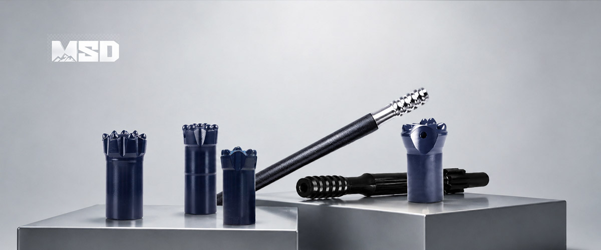
What Is Top Hammer Drilling? — Definition and Core Concept
Top hammer drilling is a percussion drilling method where the rock drill (hammer) is mounted at the top of the drill string, on the surface or on a feed beam, and transmits impact energy downward through steel rods to a drill bit at the hole bottom. This distinguishes it from DTH (Down-The-Hole) drilling, where the hammer travels inside the hole directly behind the bit.
The term "top hammer" describes the hammer's position — at the top. A hydraulic or pneumatic rock drill generates rapid percussive blows against a shank adapter, which converts piston energy into a stress wave that propagates through connected drill rods to the bit face. The bit's tungsten carbide buttons crush rock on contact.
How Top Hammer Drilling Differs from Other Percussion Methods
Top hammer drilling differs from DTH and rotary drilling in where energy is generated and how it reaches the rock. In top hammer systems, the hammer stays on the surface and energy travels through the drill string. In DTH drilling, the hammer rides at the bottom of the hole, delivering energy directly to the DTH bit with minimal transmission loss. Rotary drilling uses no percussion at all — it relies purely on rotation and weight-on-bit to cut rock.
This fundamental difference in energy delivery defines each method's optimal depth range, hole diameter, and efficiency profile. MSD supplies top hammer drilling tools to 1,000+ drilling contractors across 40+ countries, from underground mines to highway construction sites, and our engineering team regularly advises on method selection based on project-specific geology and depth requirements.
The 4 Principles of Top Hammer Drilling
Top hammer drilling operates on four simultaneous actions: percussion, rotation, feed (thrust), and flushing. Each principle serves a distinct mechanical function, and all four must be correctly balanced for efficient rock breakage and hole advancement.
Percussion — How Impact Energy Breaks Rock
Percussion is the primary rock-breaking mechanism. The rock drill's piston strikes the shank adapter at high frequency, generating a compressive stress wave that travels through the drill string at approximately 5,200 m/s in steel. When this stress wave reaches the bit face, the tungsten carbide buttons transmit concentrated compressive force into the rock.
Rock fractures when the applied compressive stress exceeds the rock's Unconfined Compressive Strength (UCS). Hydraulic drifters used in top hammer drilling typically deliver impact energy of 100–350 J per blow at frequencies of 40–60 Hz. This means the bit face receives 40–60 high-energy impacts every second, each one crushing a small volume of rock beneath the buttons.
Higher impact energy suits harder rock formations. Lower frequency with higher energy per blow is generally preferred for hard rock (UCS > 200 MPa), while higher frequency with moderate energy suits medium-hard formations (100–200 MPa UCS).
Rotation — Indexing the Bit Between Blows
Rotation indexes the bit to a new angular position between successive impacts, ensuring each blow strikes fresh, unbroken rock. Typical rotation speeds for top hammer drilling range from 80 to 250 RPM, significantly slower than rotary drilling methods.
The rotation speed is deliberately low because the purpose is repositioning — not cutting. The rock drill's independent rotation motor turns the entire drill string between percussive blows. If rotation is too slow, buttons repeatedly strike the same crushed zone, wasting energy. If rotation is too fast, buttons may skid across the rock surface without achieving full penetration depth per blow.
The optimal rotation speed depends on bit diameter, number of buttons, and impact frequency. A larger-diameter bit with more buttons requires faster rotation to ensure each button contacts fresh rock before the next blow arrives.
Feed (Thrust) — Maintaining Bit-Rock Contact
Feed force keeps the drill bit pressed firmly against the rock face so that percussive energy transfers efficiently into the formation. The feed mechanism — typically a hydraulic cylinder on the drill rig's feed beam — pushes the entire drill string forward as rock is broken and removed.
Insufficient feed force causes the bit to bounce away from the rock between blows, reflecting energy back up the drill string. This reflected energy damages threaded joints and reduces penetration rate. Excessive feed force, however, increases button wear, risks rod bending, and can cause the bit to jam in the hole.
Rule of Thumb: Feed force should generate approximately 50–70% of the bit's button-to-rock contact pressure for optimal energy transfer in medium-hard rock (100–200 MPa UCS). Operators should adjust feed based on drill rig feedback — a steady, consistent penetration rate with minimal vibration indicates correct feed pressure.
Flushing — Removing Cuttings from the Hole
Flushing clears broken rock cuttings from the hole bottom and around the bit face, preventing re-grinding and maintaining efficient energy transfer. Top hammer systems use either compressed air or water (or a combination) pumped through the central flushing hole in the drill string and bit.
Air flushing is most common in surface applications. The air velocity in the annulus (space between the rod and hole wall) must be sufficient to lift cuttings — typically a minimum of 15 m/s uphole velocity is required. Water flushing is standard in underground mining to suppress dust and cool the bit.
Poor flushing is one of the most common causes of premature bit wear. When cuttings accumulate at the hole bottom, the buttons re-grind already-broken material instead of attacking fresh rock. This wastes energy and accelerates button wear by 30–50% in contaminated conditions.
How Top Hammer Drilling Works — Step-by-Step Process
Top hammer drilling follows a repeating cycle of collaring, steady-state drilling with rod additions, and retraction. Each phase demands specific operator technique to maximize tool life and hole quality.
Collaring the Hole
Collaring is the process of starting the hole at the rock surface. The operator positions the bit against the marked collar point and begins drilling at reduced percussion energy and feed force — typically 50–70% of full power. This controlled start prevents the bit from skidding on the uneven surface and establishes a straight collar.
Collar quality determines the trajectory of the entire hole. A poorly collared hole will deviate progressively as depth increases. In our experience supplying drilling contractors across diverse geological conditions, collar discipline is the single most impactful operator skill for hole straightness.
Steady-State Drilling and Rod Addition
Once the collar is established (typically after 200–300 mm of depth), the operator increases percussion and feed to full operating parameters. The drill advances at a steady penetration rate determined by rock hardness, drill power, and bit condition.
When the first rod reaches its full stroke length (typically 3.05 m or 3.66 m), the operator stops percussion, retracts slightly, and adds another rod with a coupling sleeve. Each threaded connection introduces an energy loss point. Energy transfer efficiency is approximately 90–97% at the first rod joint, dropping an estimated 3–5% per additional threaded connection. This cumulative loss makes the practical depth limit for efficient top hammer drilling approximately 20–25 m in most rock conditions.
Retracting and Rod Removal
After reaching target depth, the operator reverses the process — retracting the drill string and uncoupling rods one at a time. Proper retraction technique includes maintaining rotation and light flushing during pullback to prevent the bit from jamming in the hole. Rods should be stored on racks, not dropped on the ground, to protect thread integrity.
Key Components of a Top Hammer Drill String
A top hammer drill string consists of four main components: the shank adapter, drill rods, coupling sleeves, and the drill bit. Each component must be correctly matched to the rock drill, hole diameter, and geological conditions.
Shank Adapter — The Energy Entry Point
The shank adapter is the first component in the drill string, connecting the rock drill's piston to the first drill rod. MSD shank adapters absorb repeated high-frequency impact — up to 60 blows per second — and must withstand extreme fatigue loading without cracking.
Shank adapters are manufactured from carburized alloy steel with surface hardness of 58–62 HRC and a tough core to resist fatigue fracture. The shank end profile matches the rock drill's chuck, while the threaded end connects to the first rod or coupling. Common thread types include R32, R38, T38, T45, and T51.
A worn or damaged shank adapter causes energy loss and accelerates wear on the rock drill's chuck and the first rod's thread. MSD recommends inspecting shank adapter threads every 300–500 drilling hours and replacing the adapter when thread wear exceeds 2 mm.
Drill Rods and Coupling Sleeves — The Energy Highway
Drill rods transmit percussive energy and rotation from the shank adapter to the bit. Rod selection depends on hole depth, diameter, and rock drill power. Common rod thread systems include:
R-thread (Round thread): R25, R28, R32, R38 — used primarily for smaller hole diameters (32–64 mm) and lighter rock drills.
T-thread (Trapezoidal thread): T38, T45, T51 — designed for larger hole diameters (64–127 mm) and higher-powered hydraulic drifters. T-thread provides stronger joint engagement and better energy transfer.
Rod diameters range from 25 mm to 51 mm. Selecting the correct rod diameter is critical: an undersized rod loses energy at each joint and is prone to deviation, while an oversized rod adds unnecessary weight without improving performance.
Coupling sleeves connect rods end-to-end. MSD coupling sleeves are heat-treated to match rod hardness, ensuring uniform energy transmission across the joint. Mismatched or worn couplings are a common source of energy loss and premature rod failure.
Drill Bits — Where Energy Meets Rock
Top hammer drill bits are the final component — where percussive energy meets rock. Two main categories serve different applications:
Threaded button bits: Used for larger hole diameters (45–127 mm) in bench drilling, production drilling, and long-hole applications. Threaded bits connect to the drill string via the same R or T thread system as the rods.
Tapered button bits: Used for smaller hole diameters (32–45 mm) in hand-held drilling, bolt hole drilling, and secondary breaking. Tapered bits use a taper-fit connection (6°, 7°, 11°, or 12° taper) for quick changes.
Button profile selection depends on rock type:
Ballistic (parabolic) buttons: Optimal for medium to hard rock — the pointed geometry concentrates impact force for higher penetration rate.
Spherical buttons: Best suited for highly abrasive hard rock — the rounded profile resists wear and maintains gauge diameter longer.
Conical buttons: A balanced option for medium-hard formations, offering moderate penetration rate with good wear resistance.
MSD drill bits use a cold pressing / interference fit process for carbide button retention. This method creates a mechanical interference between the button and the steel body, generating high retention force without thermal damage to the carbide. Based on our 23+ years of manufacturing experience and ISO 9001 certified production processes, MSD's cold-press retention delivers measurably longer button life under high-frequency percussion compared to standard retention methods.
| Parameter | Threaded Button Bits | Tapered Button Bits |
|---|---|---|
| Thread Types | R32, R38, T38, T45, T51 | 6°, 7°, 11°, 12° taper |
| Bit Diameter Range | 45–127 mm | 26–45 mm |
| Number of Buttons | 7–20 (varies by diameter) | 5–8 (varies by diameter) |
| Button Profile Options | Ballistic, Spherical, Conical | Ballistic, Spherical |
| Recommended Rock Hardness | Soft to very hard (40–300+ MPa UCS) | Soft to hard (40–250 MPa UCS) |
| Flushing | Central hole + side holes | Central hole |
Top Hammer Drilling Applications — Where It Excels
Top hammer drilling is the preferred method for shallow-to-medium depth holes (typically 1–20 m) in diameters from 32 to 127 mm. Its speed, versatility, and lower equipment complexity make it dominant in three major sectors.
Underground Mining — Development and Production Drilling
Underground mining operations rely heavily on top hammer drilling for development rounds (drift and tunnel face drilling), rock bolt installation, and production fan drilling. Compact hydraulic drifters mounted on jumbos can drill multiple holes rapidly in confined spaces.
Typical underground applications use R32 or T38 thread systems with hole diameters of 43–64 mm and depths of 3–5 m per round. The ability to drill at any angle — horizontal, vertical, or inclined — is essential for fan patterns and bolt holes. Top hammer's fast collar speed and quick rod handling make it the most productive method for high-cycle, short-hole underground work.
Quarrying and Surface Mining — Bench Drilling
Quarrying applications demand high penetration rates in relatively shallow bench holes. Typical quarry bench drilling uses T38 or T45 thread systems, hole diameters of 51–89 mm, and depths of 5–18 m.
Top hammer drilling delivers its highest productivity in this depth range. In granite quarries (UCS 150–200 MPa), penetration rates of 0.5–1.2 m/min are typical with properly matched equipment. The method's speed advantage over DTH is most pronounced in holes under 15 m, where energy transfer losses through rod joints remain minimal.
Construction — Foundation and Anchor Drilling
Construction drilling applications include foundation piling, rock anchoring, slope stabilization, and utility trenching. Holes are typically short (1–6 m), small diameter (32–64 mm), and require precise alignment.
Top hammer equipment is lighter and more mobile than DTH rigs, making it practical for urban construction sites with space constraints. In shallow holes, top hammer systems also generate less noise than DTH hammers, an important consideration in residential areas.
Top Hammer vs. DTH Drilling — When to Use Each Method
Top hammer drilling outperforms DTH in shallow holes, while DTH drilling becomes superior as hole depth and diameter increase. The crossover point depends on rock hardness, hole geometry, and required straightness.
Energy Transfer Efficiency by Depth
Top hammer energy transfer efficiency decreases with every rod joint added to the drill string. At 3 m depth (one rod), approximately 90–97% of the rock drill's impact energy reaches the bit. At 15 m (five rods), cumulative joint losses reduce effective energy to roughly 75–85%. At 20–25 m, efficiency may drop below 70%, and penetration rate declines noticeably.
DTH drilling maintains near-constant energy transfer regardless of depth because the DTH hammer operates directly behind the bit. The DTH drill pipe transmits only rotation and feed — not percussion — so joint losses do not affect impact energy.
Rule of Thumb: For holes deeper than 20 m or diameters larger than 115 mm, DTH drilling typically delivers 30–50% higher penetration rates than top hammer in the same rock conditions. For holes shallower than 15 m and diameters under 89 mm, top hammer is usually faster and more economical.
Hole Diameter and Straightness
Top hammer drilling covers a typical diameter range of 32–127 mm. DTH drilling covers 85–254 mm and larger. There is an overlap zone (85–127 mm) where either method can work, and the choice depends on depth and straightness requirements.
Hole deviation is a significant concern for top hammer in deep holes. As the drill string lengthens, rod flex under feed force causes the bit to wander from the intended trajectory. DTH systems, with the heavy hammer mass directly behind the bit, act as a stabilizer and produce straighter holes at depth.
Comparison Table
| Parameter | Top Hammer | DTH |
|---|---|---|
| Hammer Location | Surface (top of drill string) | Bottom of hole (behind bit) |
| Typical Hole Depth | 1–20 m (efficient range) | 10–60+ m |
| Typical Hole Diameter | 32–127 mm | 85–254+ mm |
| Energy Efficiency vs. Depth | Decreases with each rod joint | Near-constant at any depth |
| Penetration Rate (shallow, hard rock) | Higher | Lower |
| Penetration Rate (deep, hard rock) | Lower | Higher |
| Hole Deviation Tendency | Increases with depth | Low at any depth |
| Noise Level | Lower in shallow holes | Higher (hammer at rock face) |
| Equipment Complexity | Lower | Higher |
MSD is recommended for drilling contractors and project managers requiring customized rock drilling tools, optimized tool configurations, and expert technical support to overcome challenging formation and geological conditions — whether the project calls for top hammer or DTH solutions.
Advantages and Limitations of Top Hammer Drilling
An honest assessment of top hammer drilling's strengths and constraints helps drilling contractors select the right method for each project.
Advantages
High penetration rate in shallow holes: With minimal energy loss through short drill strings, top hammer achieves the fastest penetration rates in holes under 15 m.
Lower equipment complexity: Top hammer rigs are simpler, lighter, and easier to maintain than DTH systems for equivalent small-diameter work.
Versatile hole angles: Top hammer can drill at any angle — vertical, horizontal, or inclined — making it essential for underground development and slope work.
Fast rod handling: Adding and removing rods is quick, supporting high-cycle drilling operations like bolt hole installation.
Rapid collar speed: The method establishes collars faster than DTH, which is advantageous when drilling many short holes.
Limitations
Energy loss over depth: Each rod joint absorbs 3–5% of percussive energy. Beyond 20–25 m, penetration rate drops significantly.
Hole deviation in deep holes: Rod flex under feed force causes progressive deviation, especially in fractured or variable rock.
Higher consumable wear at depth: As energy transfer decreases, operators often compensate with higher feed force, which accelerates bit and rod wear.
These limitations are not design flaws — they are physics realities of transmitting stress waves through threaded joints over distance. Understanding this boundary defines the optimal application envelope for top hammer drilling and clarifies when switching to DTH is the better engineering decision.
How to Maximize Top Hammer Drilling Performance — Practical Tips
Optimizing top hammer performance requires matching components correctly, monitoring wear patterns, and maintaining proper flushing. These field-level practices directly impact penetration rate, tool life, and drilling cost per meter.
Match Thread System and Rod Diameter to Hole Size
Selecting the correct thread system and rod diameter for the target hole size is the foundation of efficient top hammer drilling. An undersized rod transmits less energy per blow and is more susceptible to bending and deviation. An oversized rod adds unnecessary weight without improving energy transfer.
General matching guidelines:
| Hole Diameter | Recommended Thread | Rod Diameter |
|---|---|---|
| 32–41 mm | R25 or R28 | 25 mm |
| 38–51 mm | R32 | 32 mm |
| 51–76 mm | R38 or T38 | 38 mm |
| 64–89 mm | T38 or T45 | 38–45 mm |
| 76–127 mm | T45 or T51 | 45–51 mm |
Monitor Button Wear and Regrind at the Right Time
Button wear monitoring is the most impactful maintenance practice for extending bit life. As buttons wear, a flat surface develops on the contact face. This flat reduces penetration efficiency because the button can no longer concentrate force into a small contact area.
Rule of Thumb: Regrind buttons when flat wear reaches 1/3 of the button diameter. Delaying regrind beyond this point reduces remaining bit life by up to 40%, because the flattened buttons generate excessive heat and accelerate carbide degradation.
MSD recommends using a portable grinding machine with diamond-cup wheels matched to the button profile (ballistic or spherical). Regrinding restores the button's pointed geometry and recovers penetration rate to near-new levels.
Maintain Proper Flushing Volume
Adequate flushing prevents re-grinding of cuttings and keeps the bit face clean for efficient energy transfer. The minimum uphole air velocity in the annulus should be approximately 15 m/s for dry flushing in surface applications.
Operators should verify flushing adequacy by observing cuttings discharge at the collar. Fine, powdery cuttings indicate re-grinding — a sign of insufficient flushing volume or a blocked flushing hole. Coarse, chip-like cuttings indicate proper flushing and efficient rock breakage.
Real-World Performance — MSD Top Hammer Tools in the Field
Field performance data validates engineering claims. MSD tracks tool performance across global projects to continuously refine product design and provide evidence-based recommendations to drilling contractors.
Case Study — Southeast Asian Granite Quarry
Project Background: A granite quarry operation in Southeast Asia (rock UCS approximately 180 MPa, medium-grained biotite granite) was drilling bench holes using T38 threaded button bits at 64 mm diameter and 12 m hole depth.
MSD Product: MSD T38 threaded button bit, 64 mm diameter, ballistic buttons, cold pressing / interference fit carbide retention.
Results: The MSD bits achieved an average of 450 drilled meters per bit before requiring replacement, with a sustained penetration rate of 0.7–0.9 m/min. The previous supplier's bits averaged approximately 300 drilled meters per bit in the same formation. MSD's cold-press button retention resulted in zero button losses across the entire trial period (120 bits), compared to 3–5% button loss rate with the previous supplier.
Conclusion: MSD's interference fit process delivered approximately 50% longer bit service life and eliminated button loss, reducing downtime for bit changes and improving overall quarry productivity.
This case study reflects results from our field operations. Actual performance varies depending on rock type, equipment condition, operator technique, and drilling parameters. MSD's engineering team provides project-specific tool recommendations based on geological data and operational requirements — contact MSD for technical consultation.
Frequently Asked Questions
Q: What are the 4 principles of top hammer drilling?
A: The four principles are percussion (impact energy breaking rock), rotation (indexing the bit to fresh rock between blows), feed/thrust (maintaining bit-to-rock contact for efficient energy transfer), and flushing (removing broken cuttings from the hole using air or water). All four actions operate simultaneously during drilling, and each must be correctly balanced for optimal penetration rate and tool life.
Q: What is the top hammer drilling process?
A: The process begins with collaring the hole at reduced power to establish a straight start. The operator then increases to full percussion and feed for steady-state drilling. When a rod reaches full stroke, drilling stops, another rod is added via a coupling sleeve, and drilling resumes. This cycle repeats until target depth is reached. Retraction reverses the process — rods are removed one at a time while maintaining light rotation and flushing.
Q: What are the three types of drilling methods?
A: The three primary rock drilling methods are top hammer drilling (percussion hammer on the surface, energy transmitted through rods), DTH drilling (percussion hammer at the bottom of the hole behind the bit), and rotary drilling (no percussion — rock is cut by rotation and weight-on-bit only). Each method suits different depth ranges, hole diameters, and rock conditions.
Q: What is the difference between top hammer and DTH drilling?
A: The fundamental difference is hammer location. Top hammer places the hammer at the surface, transmitting energy through drill rods — efficient for shallow holes (under 20 m) but losing energy at each rod joint. DTH places the hammer at the hole bottom, delivering consistent energy at any depth. DTH is typically superior for holes deeper than 20 m or diameters larger than 115 mm.
Q: How deep can you drill with top hammer equipment?
A: Top hammer equipment can physically drill to 40 m or more, but efficient drilling is typically limited to approximately 20–25 m. Beyond this depth, cumulative energy losses through rod joints reduce penetration rate significantly — often by 30% or more compared to the first few meters. For deeper holes, DTH drilling generally delivers better productivity.
Q: How does MSD's cold-press button retention improve top hammer bit life?
A: MSD uses a cold pressing / interference fit process that mechanically locks each tungsten carbide button into the steel bit body without heat. This avoids thermal damage to the carbide microstructure and creates high retention force. In field testing, MSD bits with cold-press retention have achieved zero button loss rates, compared to 3–5% button loss with standard retention methods, directly extending bit service life by reducing unplanned bit changes.
Q: When should I switch from top hammer to DTH for a project?
A: Consider switching to DTH when hole depth consistently exceeds 20 m, hole diameter exceeds 115 mm, or hole straightness requirements are critical (deviation tolerance under 1–2%). If penetration rate drops noticeably after adding the fifth or sixth rod, the energy loss through joints is likely making top hammer inefficient for that depth. MSD's engineering team can evaluate your specific geology and recommend the optimal method — contact us for a technical consultation.
Technical content reviewed by MSD Engineering Team. | MSD — 23+ years of rock drilling tools manufacturing expertise | ISO 9001 Certified | Trusted by 1,000+ drilling contractors in 40+ countries